6.1 Indirizzamento scheda base
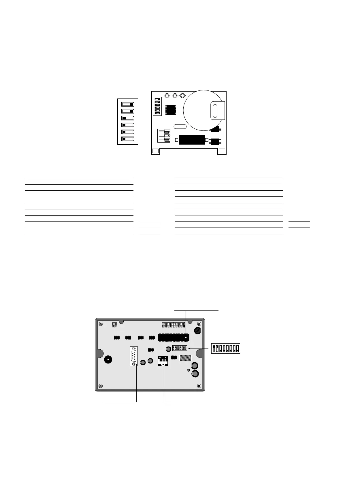
Scheda opzione rete (PCOADR0000 / PCOCLKMEM0)
La scheda opzione rete è disponibile in due versioni:
• solo dipswitch e LED - cod.: PCOADR0000
• dipswitch, LED e orologio calendario ed EEPROM
(memoria permanente) - cod.: PCOCLKMEM0
La scheda di indirizzamento è indispensabile per il funzionamento in
rete delle schede pCO.
L’indirizzo è impostabile nel range 1-16 utilizzando i dipswitch 1-5.
Il valore dell’indirizzo si ottiene tramite le seguenti tabelle:
Formula:
indir. =p(SW1)+p(SW2)+p(SW3)+p(SW4)+p(SW5);
esempio applicativo - predisposizione di addr. 19:
19=1+2+16= p(SW1)+p(SW2)+p(SW5).
*AVVERTENZA: il dip-switch n. 6 del pCO non è collegato e quindi la
sua posizione è ininfluente.
6.2 Indirizzamento terminali
Scheda terminale vista posteriormente
L’indirizzo dei terminali si imposta tramite il banco di dipswitch posti sul
retro. L’indirizzo è impostabile nel range 1-16 utilizzando i dipswitch 1-4.
Il valore dell’indirizzo si ottiene tramite le tabelle del paragrafo precedente.
Il terminale grafico non necessita dell’indirizzamento in quanto
l’indirizzo viene stabilito dalla EPROM di programma.
AVVERTENZA IMPORTANTE: se il programma applicativo non è pre-
visto in rete locale pLAN, i dip-switch devono essere posizionati su 0,
pena il non funzionamento del programma.
6.1 Addressing the main board
Optional network card (PCOADR0000 / PCOCLKMEM0)
The optional network card is available in two versions:
• dip-switch and LED only - code: PCOADR0000
• dip-switch, LED and calendar clock plus EEPROM
(permanent memory) - code: PCOCLKMEM0
The addressing card is fundamental for the pCO boards to function in a
network.
The address can be set in the range 1-16 using dip-switches 1-5.
The value of the address is calculated using the following tables:
Formula:
address =p(SW1)+p(SW2)+p(SW3)+p(SW4)+p(SW5);
application example - address 19 set up:
19=1+2+16= p(SW1)+p(SW2)+p(SW5).
*WARNING: pCO n. 6 dip-switch is not connected, so its position is of
no consequence.
6.2 Addressing the terminals
Terminal board, rear view
The address of the terminals is set using the dip-switches at the rear.
The address can be set in the range 1-16 using dip-switches 1-4.The
value of the address is calculated using the tables in the previous paragraph.
The graphic terminal does not need to be addressed as the
address is established by the program EPROM.
IMPORTANT: if the application program is not fit for pLAN local
network, the dip-switches must be placed on 0, otherwise the program
does not run
20

 Loading...


