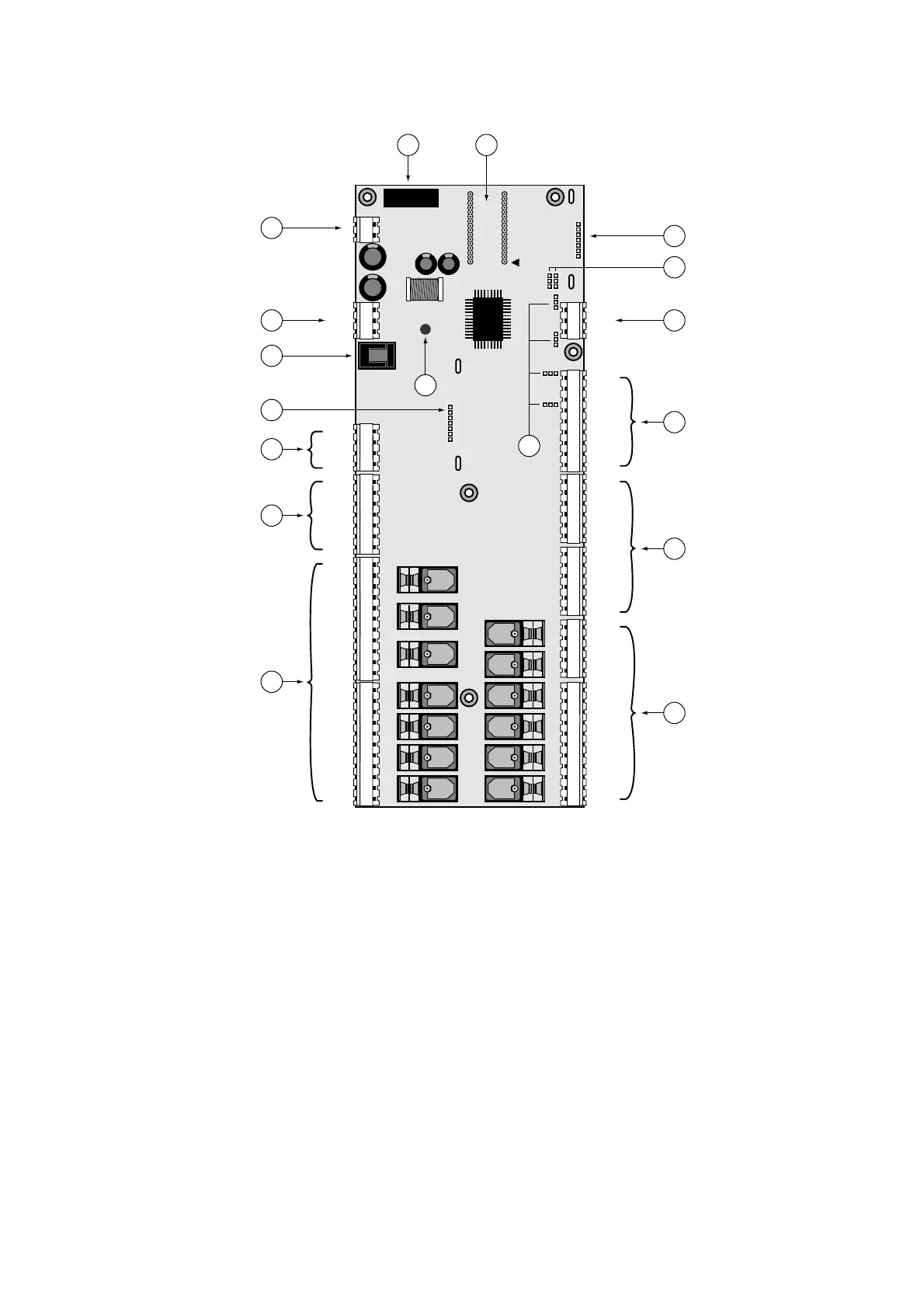
2.2 pCO Scheda Base - Planimetria
Di seguito viene fornita una descrizione della scheda base del pCO
con riferimento alla planimetria essenziale:
Riferimenti
1. Connettore per alimentazione 24 Vac, 50/60 Hz, 15 VA, oppure
24 Vdc, 10 W (vedi paragrafo “Alimentazione”).
2. Connettore per collegamento schede pCO alla rete pLAN.
3. Connettore tipo telefonico per connessione a terminale utente
(PCOT*, PCOI*) o rete locale.
4. LED giallo indicante presenza rete di alimentazione.
5. Fusibile 250 Vac, 2 A ritardato (T2A).
6. EPROM contenente il programma applicativo.
7. Connettore per l’inserimento delle schede opzionali:
indirizzamento/orologio a tempo reale.
8. Connettore per l’inserimento delle schede opzionali RS422 o RS485
per connessione alla linea seriale CAREL di supervisione e/o
teleassistenza.
9. Ponticelli per la selezione delle modalità di comunicazione delle
linee seriali:
J8: 1-2 versione 6 ingressi analogici senza UART (PCOB*00);
2-3 versione 8 ingressi analogici con UART (PCOB*21).
J9: 1-2 abilita la possibilità da parte del supervisore di resettare
la scheda pCO;
2-3 rende la scheda pCO indipendente dall’azione di reset
del supervisore. (di fabbrica)
10. Ponticelli per la selezione degli ingressi analogici: J14=B5;
J15=B6; J28=B7; J29=B8.
2.2 pCO main board - Layout
Following is a description of the pCO main board, with reference to its
basic layout:
Legend
1. Power connector for 24Vac, 50/60Hz, 15VA, or 24Vdc, 10W
(see paragraph on “power”)
2. Connector for connecting pCO boards to pLAN network.
3. Telephone-type connector for connection to user terminal (PCOT*,
PCOI*) or local network.
4. Yellow LED indicating mains power.
5. 250Vac, 2A slow-blow fuse (T2A).
6. EPROM containing the application program.
7. Connector for inserting optional cards: addressing/real-time clock.
8. Connector for inserting optional RS422 or RS485 cards for
connection to CAREL supervisory and/or telemaintenance serial
networks.
9. Jumpers for selecting the serial line communications mode:
J8: 1-2, 6 analogue input version without UART (PCOB*00)
2-3, 8 analogue input version with UART (PCOB*21)
J9: 1-2 enables pCO board resetting by the supervisor,
2-3 disables pCO board resetting by the supervisor (default).
10. Jumpers for selecting the analogue inputs: J14=B5; J15=B6;
J28=B7; J29=B8.
5

 Loading...


