7.2 Stampante seriale per display standard lcd 4x20 o 6 LED
È possibile utilizzare la stampante
seriale solo se si dispone dei
terminali pCO con i seguenti codici:
- PCOT00SCB0
terminale LCD 4x20
- PCOT00SL60
terminale LED 6 cifre
Questi terminali sono già predisposti
con un connettore a vaschetta 9
poli maschio (connettore A, Figura
32) dove collegare la stampante
tramite cavo seriale per stampante
9 poli (lato pCO) - 25 poli (lato
stampante).
Caratteristiche della stampante seriale:
Stampante con interfaccia seriale RS232
Impostazione porta seriale:
- baud-rate: 1200 - bit dati: 8
- paritá: nessuna - protocollo: handshake hardware
- bit di stop:1 o 2
Per i cavi fare riferimento agli schemi dell’opzione precedente
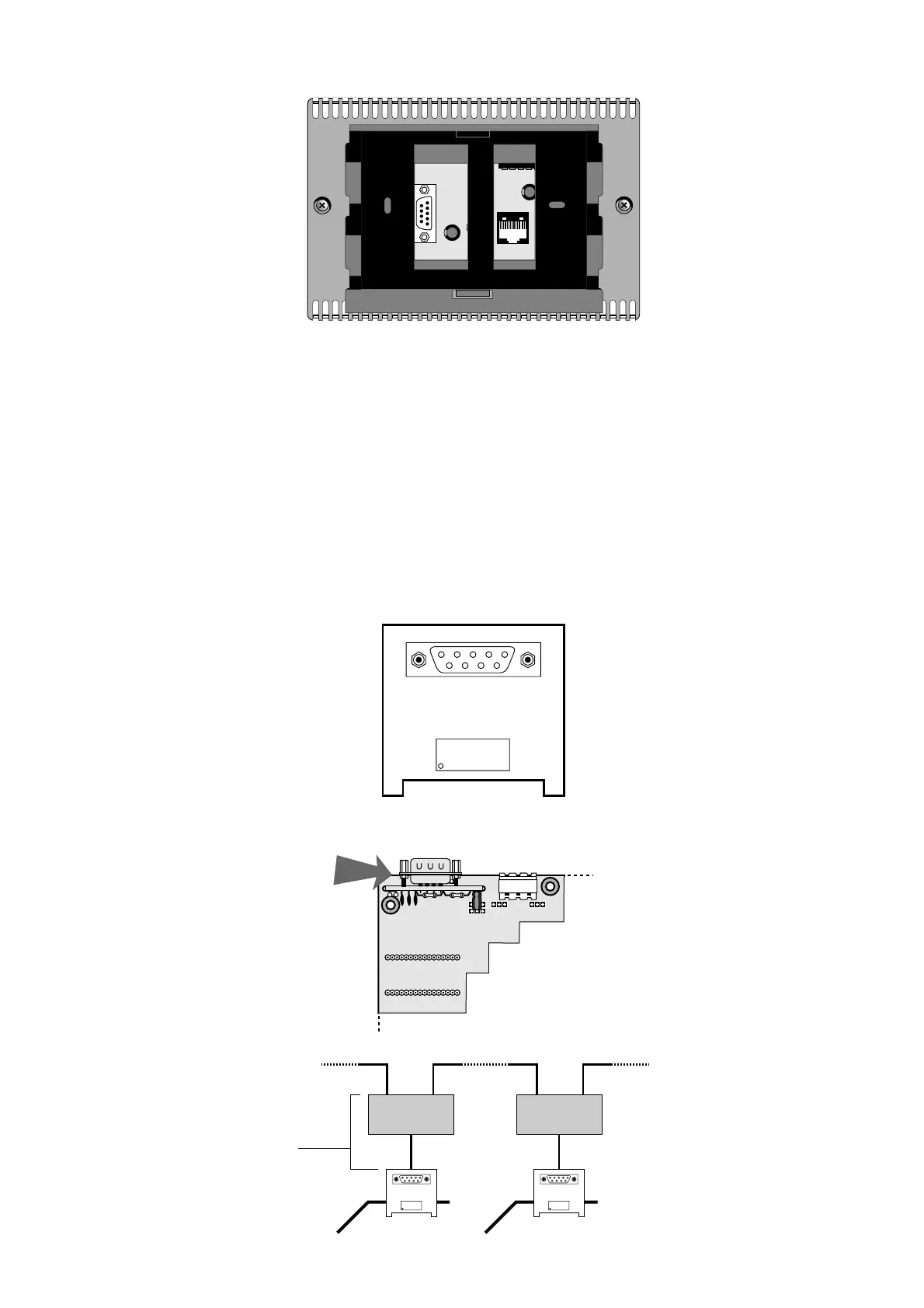
7.3 Scheda seriale per Supervisione e Teleassistenza RS422
Qui a lato in Figura 33 è indicata la schedina
seriale cod. PCOSER0000 che permette
l’interfacciamento optoisolato ad una rete
RS422 per la trasmissione dei dati. La schedina
è munita di un connettore a vaschetta 9 poli
maschio. Il collegamento alle schede si ottiene
posizionando la scheda opzionale nel
corrispondente connettore (vedi figura 33)
Piedinatura connettore RS422:
pin 1 GND
pin 2 TX+
pin 3 TX-
pin 4 RX+
pin 5 RX-
Esempio di connessione per rete
seriale RS422
7.2 Serial printer for standard 4x20 LCD or 6-LED display
A serial printer can only be used
with the following pCO terminals:
- PCOT00SCB0
terminal with 4x20 LCD
- PCOT00SL60
terminal with 6-digit LED display
This terminals are already fitted
with a 9-pin male connector (con-
nector A, Figure 32) for connecting
the printer using a serial printer
cable, 9-pin (pCO end) - 25 pin
(printer end).
Serial printer characteristics:
Printer with RS232 serial interface
Serial port settings:
- baud-rate: 1200 - data bits: 8
- parity: none - protocol: hardware handshake
- stop bits:1 or 2
Refer to the diagrams of the previous optional card for information on
the required cables.
7.3 RS422 serial card for Supervisory and Telemaintenance
networks
Figure 33 shows the serial card, code
PCOSER0000, which allows optically-insulated
interface to an RS422 network for the
transmission of data.The card is fitted with a
9-pin male connector. Connection to the boards
is made by positioning the optional card in the
corresponding connector (see figure 33)
Pin configuration, RS422 connector:
pin 1 GND
pin 2 TX+
pin 3 TX-
pin 4 RX+
pin 5 RX-
Example of an RS422 serial
network connection
25

 Loading...


