40
ICP (interstage connecting piping)
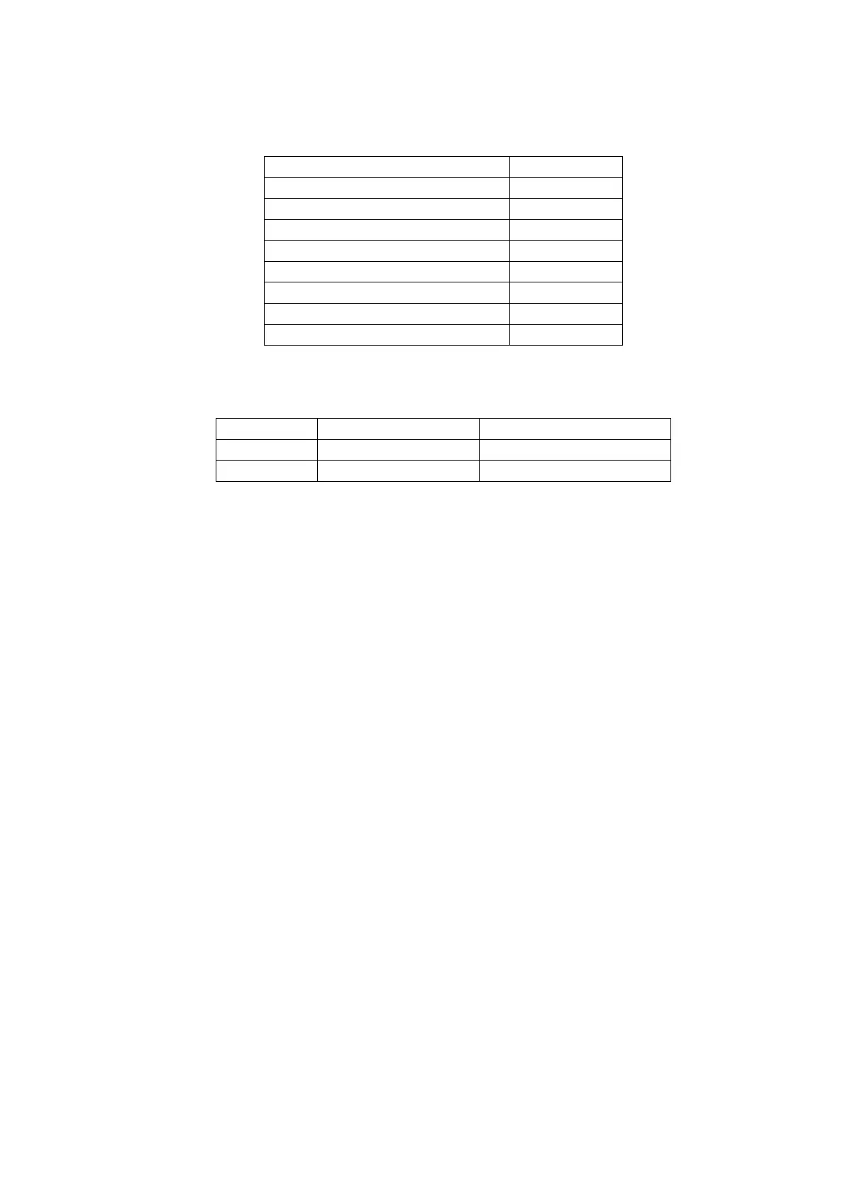
Table 10 - 19DV Piping and others weights
Envelop control & piping (kg)
Liquid bypass & isolation valve (kg)
Table 11 - 19DV accessories weight (kg)
3.3.2 - Rigging the machine components
Refer to instructions Fig. 16 and Table 2 , and Carrier Certified Prints for machine component disassembly.
IMPORTANT: Only a qualified service technician should perform this operation.
WARNING: Do not attempt to disconnect flanges while the machine is under pressure. Failure to relieve pressure
can result in personal injury or damage to the unit.
NOTE: If the cooler, economizer, and condenser vessels must be separated, the heat exchangers should be kept level
by placing a support plate under the tube sheets. The support plate will also help to keep the vessels level and aligned
when the vessels are bolted back together.
NOTE: Wiring must also be disconnected. Label each wire before removal (see Carrier Certified Prints). In order to
disconnect the VFD from the machine, remove wiring between the VFD from the machine, remove wiring between
VFD and control panel, purge system and the main motor leads at the starter lugs. Remove all transducer and
sensor wires at the sensor. Clip all wire ties necessary to pull heat exchangers apart.
To Separate Evaporator and Condenser:
1. Place a support plate under each tube sheet leg to keep each vessel level.
2. Cut tubing between high side float chamber and motor/ VFD cooling.
3. Cut tubing between high side float chamber and lube assembly.
4. Disconnect the compressor discharge pipe.
5. Disconnect bolted connection between the low side float chamber and the evaporator.
6. Disconnect bolted economizer pipe between economizer and second stage compressor inlet.
7. Cut tubing between purge and compressor volute.
8. Cut tubing between purge regeneration line and motor drain.
9. Cover all openings.
10. Disconnect all wires and cables that cross from cooler side of the machine to the condenser side.
11. Disconnect the marriage brackets connecting the evaporator and condenser tubesheets (both ends).
To Separate the Compressor from the Evaporator:
1. Unbolt motor drain flange.
2. Unbolt suction pipe flange.
3. Unbolt discharge pipe flange.
4. Cut tubing from purge to compressor volute.
5. Disconnect O-ring face seal from bearing drain (near motor drain).
 Loading...


