46
Heat exchanger
frame size
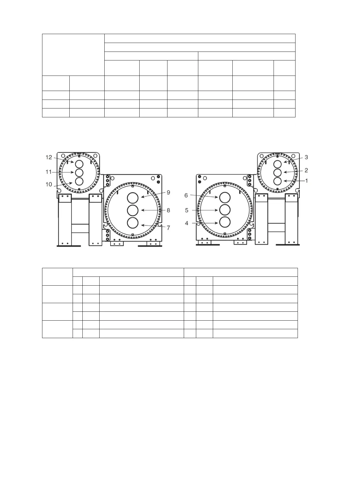
Table 12 – 19DV nozzle size
* : Refer to certified drawings
Fig. 22 - “Standard waterboxes
and nozzle arrangements”
3.5.1 Install water piping to heat exchanger
Install piping using job data, piping drawings, and procedures outlined below. A typical piping installation is
shown in Fig. 23.
CAUTION: Factory-supplied insulation is not flammable but can be damaged by welding sparks and open flame.
Protect insulation with a wet canvas cover.
CAUTION: To prevent damage to sensors, remove evaporator and condenser water temperature sensors before
welding connecting piping to water nozzles. Replace sensors after welding is complete.
 Loading...


