99
NOTE: For first stage, rotate coupling clockwise to close guide vanes; rotate coupling counterclockwise to open guide vanes.
For second stage, rotate coupling counterclockwise to close guide vanes; rotate coupling clockwise to open guide vanes.
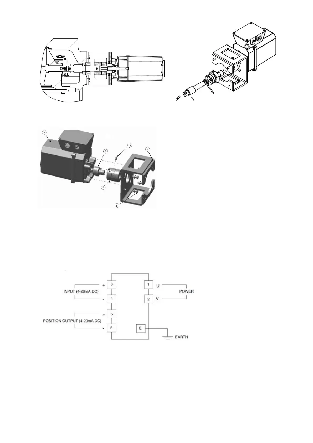
1 : actuator
2 : Connector
3 : Set screw
4 : Bracket
5 : Coupling
6 : Holddown bolts and washers
The guide vane actuator wiring of 19DV is as below :
Fig 55 – IGV actuator details
9.1.10 Trim Refrigerant Charge
If to obtain optimal chiller performance it becomes necessary to adjust the refrigerant charge, operate the chiller at
design load and then add or remove refrigerant slowly until the difference between the leaving chilled water
temperature and the cooler refrigerant temperature reaches design conditions or becomes a minimum.
Do not overcharge. Use cooler sight glass to check the liquid level. The level must be in the middle of sight glass
for correct refrigerant charge in operation. During steady state operation at 80-100% of capacity, the boiling pool
 Loading...


