62
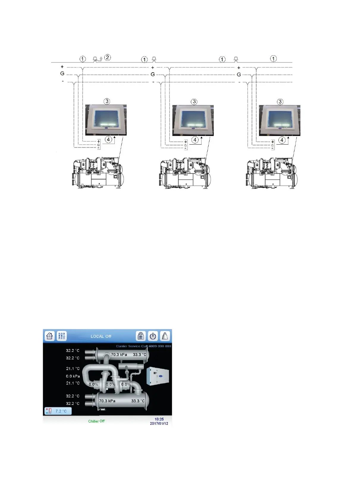
3. Crimp one no. 8 size spring spade terminal on each conductor.
4. Attach red to “+” terminal and white to “G” terminal and black to “–” terminal of CCN Network interface
located in the PIC5+ touch screen panel.
1: drain wire
2 : ground drain wire
3 : PIC5+ touch screen panel
4 : CCN wiring
______ : factory wiring
- - - - - - : field wiring
Fig 33 – CCN network wiring
4 START-UP/SHUT-DOWN/RECYCLE SEQUENCE
4.1 Local Start/Stop Control
Local start-up (or manual start-up) is initiated by pressing the gray Start/Stop icon on the HMI interface. See fig 34
Fig 34 – Chiller start/stop icon
This initiates the PIC5+ starting sequence by displaying the list of operating modes. Press Local On to initiate
start-up. See Fig. 35.
 Loading...


