49
NOTE: The dry contacts for the field inputs should be located as close to the unit as possible. The field wiring
should be capable of preventing electrical noise or induced voltage and should not be routed with any wires with
voltage over 50 v.
3.6.1 CONNECT CONTROL INPUTS
Wiring may be specified for a spare safety switch, and a remote start/stop contact can be wired to the terminal
strip. Additional spare sensors and control modules may be specified as well. Carrier Comfort Network® (CCN)
communication is wired to the machine HMI panel.
Wiring may be specified for a remote start/stop contact, a remote emergency stop contact, an ice build contact, a
spare safety switch, a power request feedback switch, a cooler water flow switch and a condenser water flow
switch can be wired to the control panel field terminal strip. Additional spare sensors may be specified for auto
demand limit input, refrigerant leak sensor, common CHWS temperature sensor, auto water temp reset and
common CHWR temp sensor can be wired to the control panel field terminal strips as well. These are wired to the
machine control panel. See electrical wiring diagrams.
3.6.2 CONNECT CONTROL OUTPUTS
Wiring maybe specified for a chiller alarm relay, a free cooling mode relay and a power request relay can be wired
to the control panel field terminal strip. Additional analog output signals may be specified for chiller running status
(on/off/ready) and head pressure output can be wired to the control panel field terminal strips as well. These are
wired to the machine control panel. See electrical wiring diagrams.
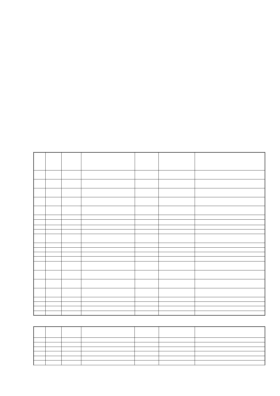
Designation for
wiring diagram
Entering chilled water
temperature
Leaving chilled water
temperature
Entering condenser water
temperature
Leaving condenser water
temperature
Evap. refrigerant liquid
temperature
Comp Discharge temperature
For freestanding VFD option - customer
terminals
User option, dry contact "Closed"
indicates "Flow" / not connected in std
User option, dry contact "Closed"
indicates "Flow" / not connected in std
User option, dry contact "Closed"
indicates Turn ON chiller
Remote emergency stop input
User option, dry contact "Closed"
indicates Chiller Emergency stop
Designation for
wiring diagram
Motor winding temperature 1
factory option / 4 - 20 mA
 Loading...


