10
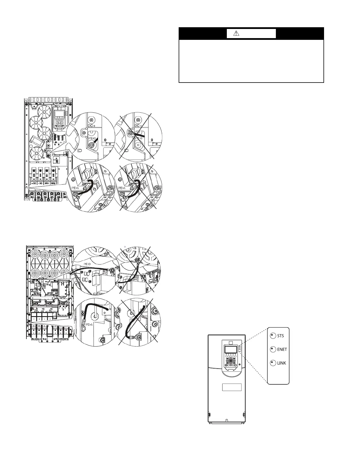
Two jumper wires connect a particular terminal to chassis ground.
The MOV and AC EMI jumper should be connected to the PE-A
terminal. The COMMON MODE CAPACITORS to GROUND
jumper should be connected to a standoff rather than the PE-B
terminal.
Use the recommended tools as follows when connecting jumper
wires in Frame 6 and in Frame 7:
• Recommended torque (screws and nuts) = 1.36 N
·
m (120.0 lb
·
in.)
• Recommended hex socket = 7 mm
• Recommended screwdriver = T20 star type
See Fig. 13 and Fig. 14 for the correct positions of the jumpers.
Fig. 13 — Jumper Wire Locations — Frame 6
Fig. 14 — Jumper Wire Locations — Frame 7
SERVICE
Troubleshooting the Drive
The drive can display 2 kinds of error codes on the HMI called
Alert and Alarm codes. These codes signal a problem detected
during self-tuning or drive operation. Note the following differ-
ences between Carrier and Allen-Bradley terminology:
• A warning message on the HMI is an ALERT.
• The same warning viewed with Rockwell Drive Explorer
is a VFD ALARM.
• A failure resulting in a shutdown is seen as an ALARM on
the HMI and as a VFD FAULT when viewed with Drive
Explorer.
CONDITION CODES
CHILLER ALERT =VFD ALARM
CHILLER ALARM =VFD FAULT
See Tables 4-5 and Fig. 15.
CHILLER ALERT CODES
An alert condition is indicated by a message on the HMI screen.
The drive will continue to operate during the alert condition. In-
vestigate the cause of the alert to ensure it does not lead to a fault
condition. The alert code will automatically be cleared from the
HMI when the condition causing the alert no longer exists. See the
19XRV or 23XRV Start-Up, Operation and Maintenance Instruc-
tions for ICVC alert codes or appropriate Controls Operation and
Troubleshooting manual for PIC6 controls.
CHILLER ALARM CODES
An alarm condition is also indicated by a message on the HMI
screen. If an alarm occurs, the drive coasts to stop. The STS (sta-
tus) light on the drive will turn from green to red or yellow (see
Table 4). The detected fault message is maintained on the display
until it is cleared by pressing the RESET softkey. See the 19XRV
or 23XRV Start-Up, Operation and Maintenance Instructions for
ICVC alarm codes or appropriate Controls Operation and Trou-
bleshooting manual for PIC6 controls.
TEST EQUIPMENT NEEDED TO TROUBLESHOOT
An isolated multimeter adequately rated for the DC bus voltage will
be needed to measure DC bus voltage and to make resistance checks.
Note that dedicated troubleshooting test points are not provided.
Fig. 15 — Drive Status Indicator
CONNECTED
DISCONNECTED
COMMON MODE
MOV
A19-2325
CONNECTED
DISCONNECTED
COMMON MODE
MOV
A19-2326
WARNING
DC bus capacitors retain hazardous voltages after input power
has been disconnected. After disconnecting input power, wait
five (5) minutes for the DC bus capacitors to discharge and
then check the voltage with a voltmeter to ensure the DC bus
capacitors are discharged before touching any internal compo-
nents. Failure to observe this precaution could result in severe
bodily injury or loss of life.
 Loading...


