18
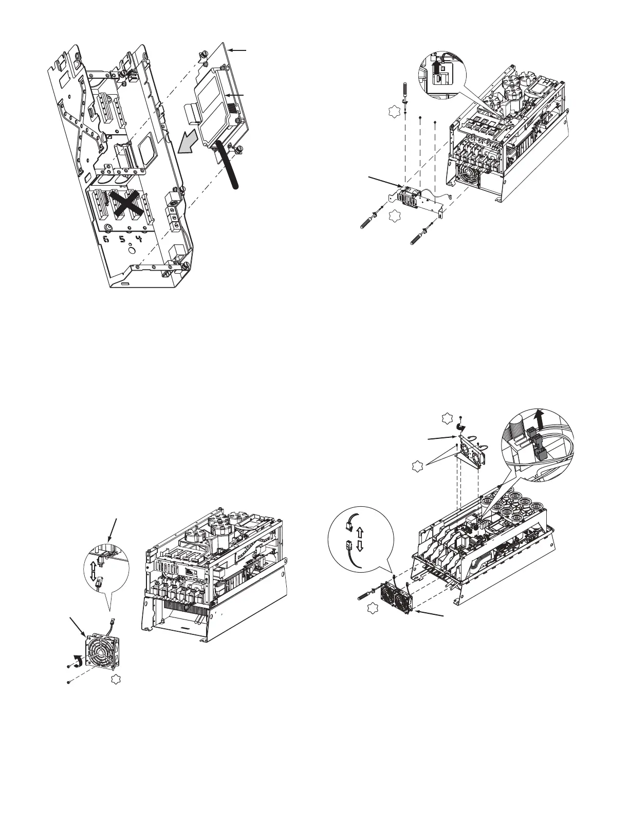
Fig. 27 — Mount COMM Card Plate to Drive
CHILL PLATE FAN AND INTERNAL FAN REPLACE-
MENT
Follow these steps to replace the chill plate fan and internal fan in
Frames 6 and 7.
Frame 6 (chill plate fan kit Z1P-FAN-A6-A):
1. Disconnect power to the drive. Before removing the enclo-
sure, open the access door on the front of the drive. See
Fig. 19.
2. Check to be sure that the voltage between DC+ and DC-
and from each DC terminal to the chassis is zero before
proceeding. See Fig. 20.
3. Remove the enclosure. See Fig. 21.
4. Remove and replace the chill plate fan. See Fig. 28.
5. Remove and replace the internal fan. See Fig. 29.
6. Install the enclosure. See Fig. 21.
Fig. 28 — Chill Plate Fan, Frame 6
Fig. 29 — Internal Fan, Frame 6
Frame 7 (chill plate fan kit Z1P-FAN-A7-A):
1. Disconnect power to the drive. Before removing the enclo-
sure, open the access door on the front of the drive. See
Fig. 19.
2. Check to be sure that the voltage between DC+ and DC-
and from each DC terminal to the chassis is zero before
proceeding. See Fig. 20.
3. Remove the enclosure. See Fig. 21.
4. Remove and replace the chill plate and internal fans. See
Fig. 30.
5. Install the enclosure. See Fig. 21.
Fig. 30 — Chill Plate and Internal Fans, Removal and
Replacement, Frame 7
Part Identification and Location
See Fig. 31-34 for parts descriptions and locations.
T20
2.6 N•m (23 lb•in.)
CHILL PLATE
FAN POWER
CONNECTION
CHILL PLATE FAN
T20
2.6 N•m
(23 lb•in.)
T20
2.6 N•m
(23 lb•in.)
INTERNAL FAN
X2
T20
5.20 N•m
(46 lb•in.)
T15
2.6 N•m (23 lb•in.)
T15
INTERNAL FANS
CHILL PLATE FANS
2.6 N•m (23 lb•in.)
 Loading...


