15
Table 6 — Diode Checks
NOTE: Digital meters require a special diode check function because
the current sourced by the meter during a normal resistance (Ohms)
test is too low to accurately test a diode. Make sure the meter is set to
the diode test function. Voltage readings may not be exact as shown in
above table, but look for consistency during each of the 4 tests. When
performing a test that should return infinity (OL) as shown in above
table, you may see a value slowly climbing toward infinity. This is a
result of the meter charging a capacitor and is normal.
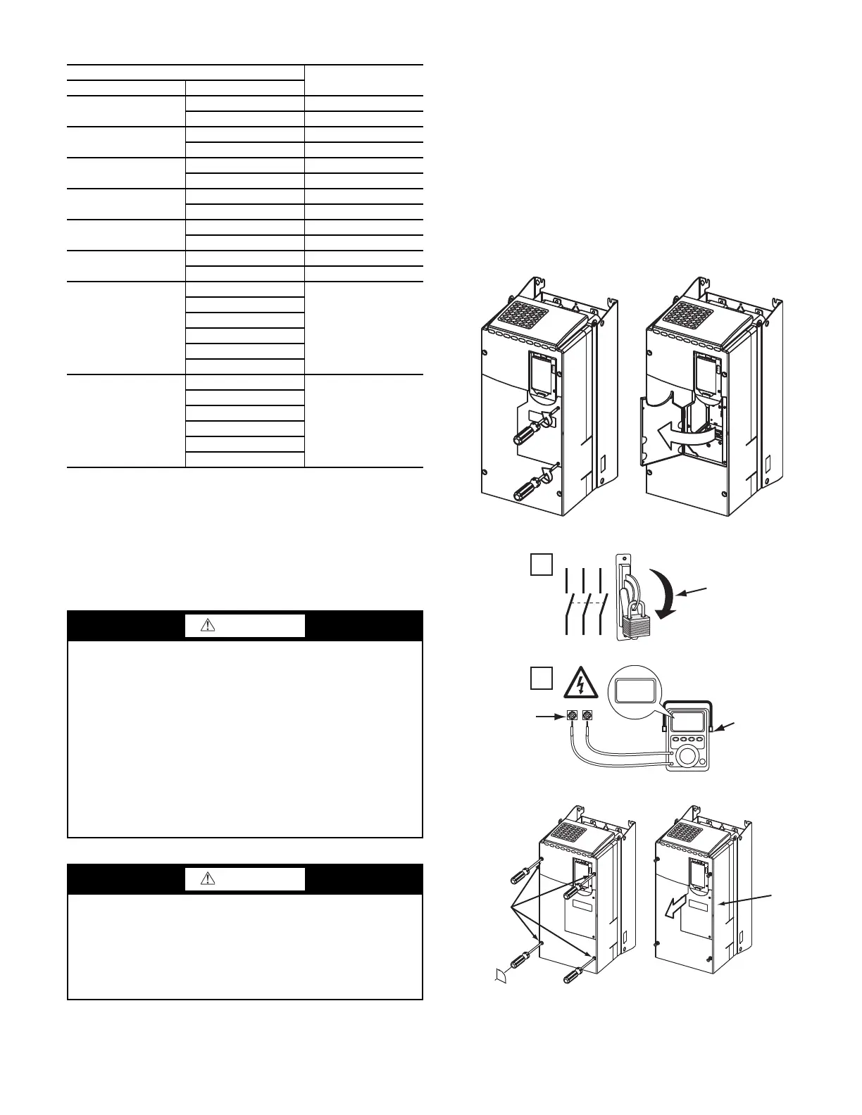
Servicing the Drive
1. Using recommended screwdriver (6.4 mm [0.25 in.] flat or
T20 star), open access door. See Fig. 19.
2. Check to be sure that the voltage between DC+ and DC-
and from each DC terminal to the chassis is zero before
proceeding. See Fig. 20.
3. Remove the enclosure. See Fig. 21.
REMOVING THE DRIVE
The dimensions and weights specified must be taken into consid-
eration when removing the drive. All lifting equipment and lifting
components (hooks, bolts, lifts, slings, chains, etc.) must be prop-
erly sized and rated to safely lift and hold the weight of the drive
while removing it. For 19XRV chillers, see Fig. 22. For 23XRV
chillers, see Fig. 23. The drive weights are as follows:
• Drive weight for Frame 6: 85 lb.
• Drive weight for Frame 7: 160 - 249 lb.
Fig. 19 — Open Access Door
Fig. 20 — Check DC Bus Terminals
Fig. 21 — Removing Enclosure
METER LEAD
METER READING
(+) (-)
R
DC+ 0.5 v
DC- Infinite (OL)
S
DC+ 0.5 v
DC- Infinite (OL)
T
DC+ 0.5 v
DC- Infinite (OL)
U
DC+ 0.5 v
DC- infinite (OL)
V
DC+ 0.5 v
DC- Infinite (OL)
W
DC+ 0.5 v
DC- Infinite (OL)
DC+
R
Infinite (OL)
S
T
U
V
W
DC-
R
0.5 v
S
T
U
V
W
WARNING
To guard against possible personal injury and/or equipment
damage:
1. Inspect all lifting hardware for proper attachment before
lifting drive.
2. Do not allow any part of the drive or lifting mechanism
to make contact with electrically charged conductors or
components.
3. Do not subject the drive to high rates of acceleration or
deceleration while transporting to the mounting location
or when lifting.
Do not allow personnel or their limbs directly underneath the
drive when it is being lifted and mounted.
WARNING
DC bus capacitors retain hazardous voltages after input power
has been disconnected. After disconnecting input power, wait
five (5) minutes for the DC bus capacitors to discharge and
then check the voltage with a voltmeter to ensure the DC bus
capacitors are discharged before touching any internal compo-
nents. Failure to observe this precaution could result in severe
bodily injury or loss of life.
1
L1 L2 L3
O
I
2
DC+ DC–
0V
0V
LOCKOUT/TAGOUT
MULTIMETER
DC BUS TEST
TERMINALS
LOCATED INSIDE
ACCESS DOOR
90°
SLIDE
ENCLOSURE
FORWARD
LOOSEN
ENCLOSURE
FASTENERS
 Loading...


