3
ABBREVIATIONS AND EXPLANATIONS
Frequently used abbreviations in this manual include:
Required Publications
The Carrier VFD option Start-Up and Service Manual must be
used with the following manuals:
• Latest version of the PowerFlex 755 AC Drives manuals
• Latest revision of the Start-Up, Operation, and Mainte-
nance Instructions for the 19XRV or 23XRV with PIC III
Controls
Getting Assistance from Rockwell Automation
Contact the local Rockwell Automation sales office with any
questions or problems relating to the products described in this
manual. For technical support on drives, call the HVAC Hotline at
1-888-926-6786, Option 1.
Before calling, have the following information available from the
Allen-Bradley data nameplate located inside the enclosure on the
right wall. See Fig. 1.
• Allen-Bradley ID or CAT. NO.
• Carrier VFD Code (Carrier Part Number)
• Allen-Bradley serial number
Fig. 1 — Allen Bradley Data Nameplate
IDENTIFYING DRIVE COMPONENTS
Chiller control schematics and VFD schematics are included in
Appendix A.
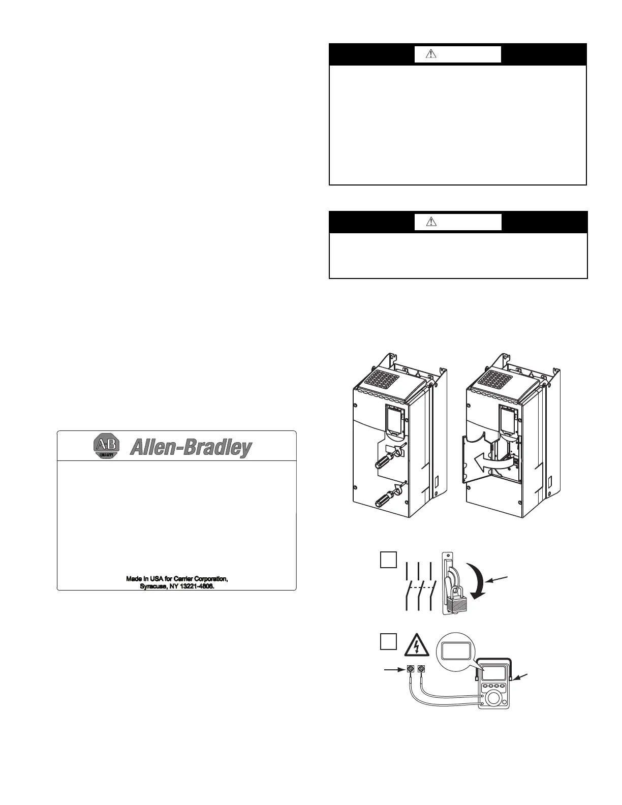
Opening the VFD Access Door
1. Using recommended screwdriver (6.4 mm [0.25 in.] flat or
T20 star), open access door. See Fig. 2.
2. Check to be sure that the voltage between DC+ and DC–
and from each DC terminal to the chassis is zero before
proceeding. See Fig. 3.
Fig. 2 — Opening Access Door
Fig. 3 — Check DC Bus Terminals
Drive Assembly Catalog Number
See Fig. 4 and 5 for examples of the Rockwell Automation Drive
Assembly Catalog Number.
CCM — Chiller Control Module
DC — Direct Current
DPI — Drive Peripheral Interface
ENET — Ethernet
HMI — Human Machine Interface
ICVC — International Chiller Visual Controller
IGBT — Insulated Gate Bipolar Transistor
I/O — Inputs/Outputs
IP — Internet Protocol
MCB — Main Control Board
MOV — Metal Oxide Varistor
PE — Protective Earthing Conductor
PIC — Product Integrated Control
PWM — Pulse Width Modulation
SIO — Sensor Input/Output
STS — Status
VFD — Variable Frequency Drive
ID No.: 21P-104773-40
Input Rating: 480VAC 454A 60Hz 3PH
Output Rating: 0-460VAC 477A 0-325Hz 3PH
Short Circuit Rating: 65kA, 480V Max.
Interrupt Capacity Rating: 100kAIC
Enclosure Type: TYPE 1
Coolant Type: Refrigerant R134a
Design Pressure: 185 PSIG
Carrier Part Number: 19XVR0445335A1F
VFD Serial Number: XXXXXXXXX
Carrier Dwg. Number: 19XV04021001
Mfd. On: 08-13-10
FAC.LOC.: 1100
Max. Ambient Temperature: 40°C
ORDER NO: 0001772838-00001
WARNING
DC bus capacitors retain hazardous voltages after input power
has been disconnected. After disconnecting input power, wait
five (5) minutes for the DC bus capacitors to discharge and
then check the voltage with a voltmeter rated for the DC bus
voltage to ensure the DC bus capacitors are discharged before
touching any internal components. Failure to observe this pre-
caution could result in severe bodily injury or loss of life.
An isolated multimeter will be needed to measure DC bus volt-
age and to make resistance checks. The drive’s DC bus capaci-
tors retain hazardous voltages after input power has been dis-
connected.
WARNING
Before removing the drive enclosure, open access door and
verify that the DC bus voltage has dropped to zero by checking
the terminals behind the access door. Failure to observe this
precaution could result in severe bodily injury or loss of life.
1
L1 L2 L3
O
I
2
DC+ DC–
0V
0V
LOCKOUT/TAGOUT
MULTIMETER
DC BUS TEST
TERMINALS
LOCATED INSIDE
ACCESS DOOR
 Loading...


