17
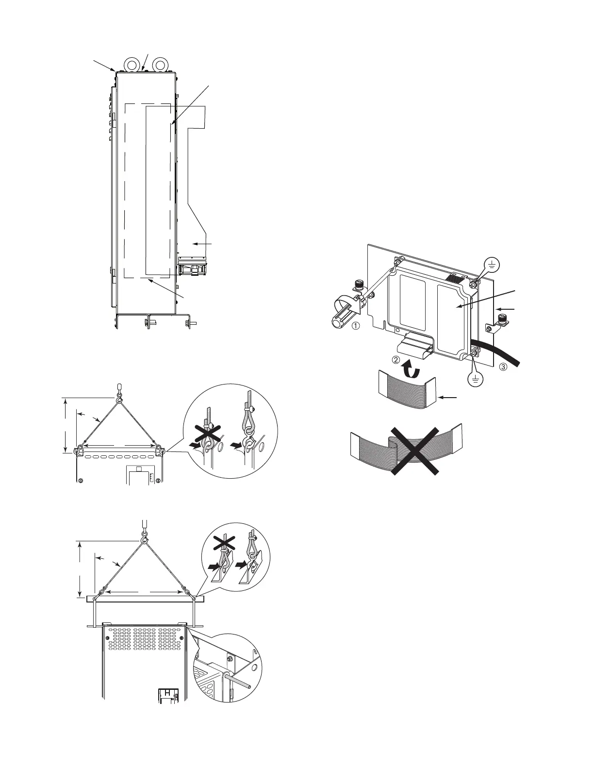
Fig. 23 — 23XRV Enclosure Access for
Removing Drive
Fig. 24 — Rigging the Enclosure, Frame 6
Fig. 25 — Rigging the Enclosure, Frame 7
REPLACING THE GATEWAY (A-B20-750-20COMM
PIC3 / 20-COMM-H (PIC6) OPTION CARD)
Follow these steps for removing and replacing the existing gate-
way:
1. Disconnect power to the drive. Before removing the enclo-
sure, open the access door on the front of the drive. See
Fig. 19.
2. Check to be sure that the voltage between DC+ and DC-
and from each DC terminal to the chassis is zero before
proceeding. See Fig. 20.
3. Remove the enclosure. See Fig. 21.
4. Remove the 2 screws securing the mounting plate and
remove the mounting plate and COMM card. See Fig. 26.
5. Mount the new COMM card and mounting plate and
attach with the 2 screws removed in Step 4. See Fig. 27.
6. Use the shorter ribbon cable to connect the plug on the
COMM card to the connector on the mounting plate. See
Fig. 26.
7. Install the enclosure. See Fig. 21.
Fig. 26 — COMM Card
DRIVE EXTENDS BEHIND
MAIN ENCLOSURE
SUPPORT FROM
BELOW
DRIVE POSITIONED FOR
VERTICAL LIFT
ENCLOSURE TOP
IS REMOVABLE
FRONT CORNER OF
DRIVE COMPARTMENT
IS REMOVABLE
SIDE VIEW
0.45-0.67 N-m
(4.0-6.0 lb.-in.)
3 PLACES
MOUNTING PLATE
GATEWAY
RIBBON CABLE
 Loading...


