11
Table 4 — Drive Status Indicator Descriptions
NOTES:
1. A Type 1 alarm indicates that a condition exists. Type 1 alarms are
user configurable.
2. A Type 2 alarm indicates that a configuration error exists and the
drive cannot be started. Type 2 alarms are not configurable.
VERIFYING THAT DC BUS CAPACITORS ARE
DISCHARGED
The drive’s DC bus capacitors retain hazardous voltages after in-
put power has been disconnected. Perform the following steps be-
fore touching any internal components:
1. Turn off and lock out input power. Wait 5 minutes.
2. Verify that there is no voltage at the drive’s input power
terminals.
3. Measure the DC bus potential with a voltmeter while
standing on a non-conductive surface and wearing insulated
gloves (1000 v). Measure the DC bus potential. See Fig. 6 for
the 248-amp drive and Fig. 7 for the 289, 361, and 477-amp
drives. The voltage between DC+ and DC-, and from each
DC terminal to the chassis must be zero before proceeding.
4. Once the drive has been serviced, reapply input power.
HIGH TEMPERATURE ALARMS
Coolant flow through the cold plate is controlled by an orifice in
the refrigerant line leaving the cold plate. The orifice looks like
one of the O-ring face seal connectors and in fact is used as one of
the connections on the coolant tubing. If the orifice is present and
condenser liquid flow is present, the liquid will flash to cooler
temperature at the orifice. This temperature difference is great
enough to be easily felt.
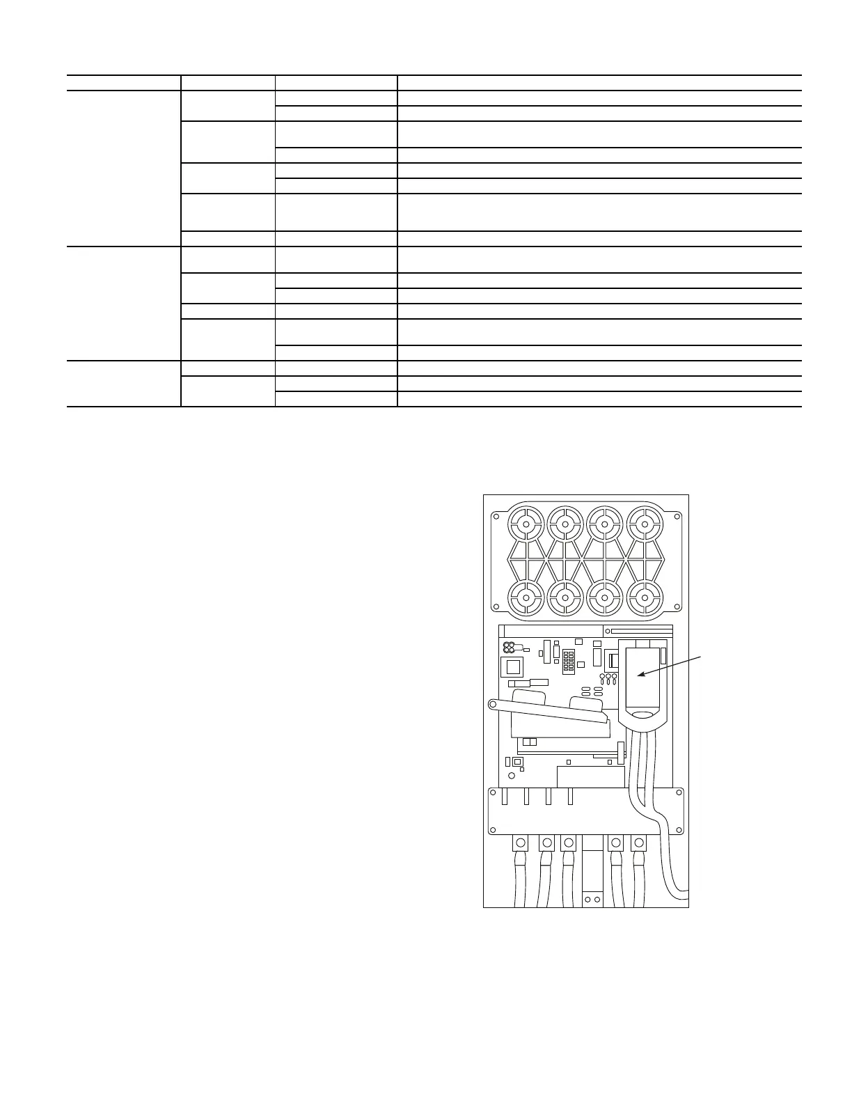
MAIN CONTROL BOARD (MCB) COMPONENTS
Figure 16 shows the drive module with the cover removed. To ac-
cess the control boards, loosen the screw on the face of the keypad
mount and swing the keypad mount upward.
The components on the main control board (MCB) are shown in
Fig. 17. Note the location of the terminals labeled MCB I/O. The
high-pressure switch is wired to these terminals as shown in
Fig. 18. In the event of a high condenser pressure alarm, the con-
nections at these terminals should be checked and tightened if
necessary.
Typical wiring schematics are shown in Appendix A.
Fig. 16 — Drive Module with Cover Removed
NAME COLOR STATE DESCRIPTION
STS (Status)
Green Flashing Drive ready but not running, and no faults are present.
Steady Drive running, no faults are present.
Yellow Flashing Drive is not running. A type 2 (non-configurable) alarm condition exists, and the
drive cannot be started.
Steady Drive is not running, a type 1 alarm condition exists. The drive can be started.
Red Flashing A major fault has occurred. Drive cannot be started until fault condition is cleared.
Steady A non-resettable fault has occurred.
Red/Yellow Flashing Alternately A minor fault has occurred. When running, the drive continues to run. System is
brought to a stop under system control. Fault must be cleared to continue. Use
parameter 950 [Minor Flt Config] to enable. If not enabled, acts like a major fault.
Green/Red Flashing Alternately Drive is flash updating.
ENET
None (Unlit) Off Adapter and/or network is not powered, adapter is not properly connected to the
network, or adapter needs an IP address.
Red Flashing An Ethernet/IP connection has timed out.
Steady Adapter failed the duplicate IP address detection test.
Red/Green Flashing Alternately Adapter is performing a self-test.
Green Flashing Adapter is properly connected but is not communicating with any devices on the
network.
Steady Adapter is properly connected and communicating on the network.
LINK
None (Unlit) Off Adapter is not powered or is not transmitting on the network.
Green Flashing Adapter is properly connected and transmitting data packets on the network.
Steady Adapter is properly connected but is not transmitting on the network.
SWING UP KEY PAD
MOUNT TO ACCESS
CONTROL BOARDS
 Loading...


