b. Connect large diameter drain tube and clamp (factory-
supplied in loose parts bag) to drain tube coupling, extend-
ing collector box drain tube.
c. Route extended tube (blue label) to condensate trap and cut
to appropriate length.
d. Clamp tube to prevent any condensate leakage.
2. Inducer Housing Drain Tube
a. Remove and discard LOWER (molded) inducer housing
drain tube which was previously connected to condensate
trap.
b. Use inducer housing drain extension tube (violet label and
factory-supplied in loose parts bag) to connect LOWER
inducer housing drain connection to the condensate trap.
c. Determine appropriate length, cut, and connect tube.
d. Clamp tube to prevent any condensate leakage.
3. Relief Port Tube
a. Extend collector box tube (green label) which was previ-
ously connected to the condensate trap by splicing to small
diameter tube (factory-supplied in loose parts bag).
b. Route extended collector box pressure tube to relief port
connection on the condensate trap.
c. Determine appropriate length, cut, and connect tube.
d. Clamp tube to prevent any condensate leakage.
CONDENSATE TRAP FIELD DRAIN ATTACHMENTS
Refer to Condensate Drain section for recommendations and
procedures.
PRESSURE SWITCH TUBING
The LOWER collector box pressure tube (pink label) is factory
connected to the pressure switch for use when furnace is installed
in UPFLOW applications. This tube MUST be disconnected,
extended, rerouted, and then reconnected to the pressure switch in
HORIZONTAL LEFT applications.
NOTE: See Fig. 10 or tube routing label on main furnace door to
check for proper connections.
Modify tube as described below.
1. Disconnect collector box pressure tube (pink label) attached to
pressure switch.
2. Use smaller diameter tube (factory-supplied in loose parts
bag) to extend tube disconnected in item 1.
3. Route extended tube:
a. Behind inducer housing.
b. Between blower shelf and inducer housing.
c. Behind inducer motor bracket.
d. Between inducer motor and pressure switch.
4. Determine appropriate length, cut, and reconnect tube to
pressure switch connection labeled COLLECTOR BOX.
CONDENSATE TRAP FREEZE PROTECTION
Refer to Condensate Drain Protection section for recommenda-
tions and procedures.
CONSTRUCT A WORKING PLATFORM
Construct working platform where all required furnace clearances
are met. (See Fig. 3 and 11.)
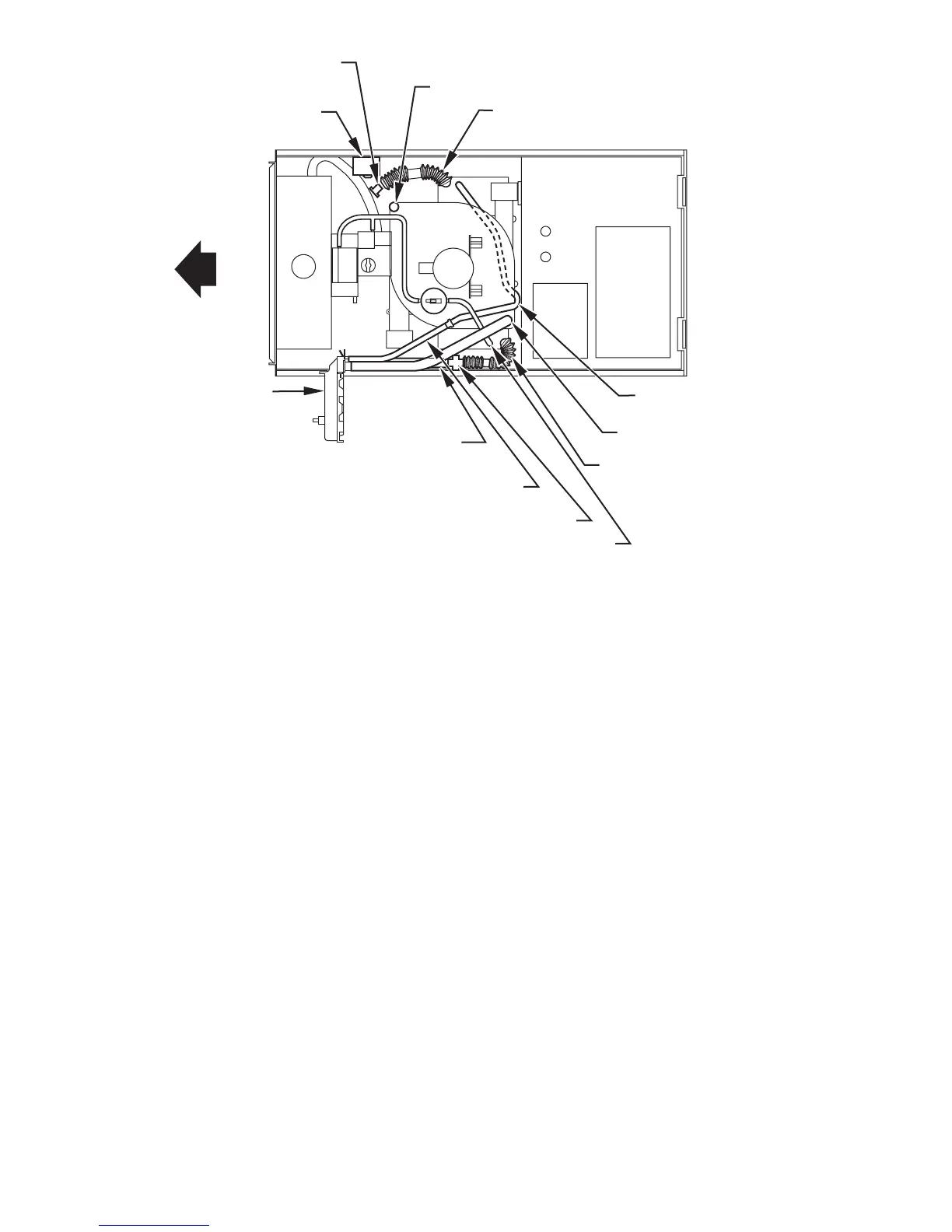
Fig. 10—Horizontal Left Tube Configuration
A00215
CONDENSATE
TRAP
AUXILIARY "J" BOX
PLUG
CAP
INDUCER HOUSING
DRAIN TUBE (VIOLET)
COLLECTOR BOX
DRAIN TUBE (BLUE)
COLLECTOR BOX TUBE (PINK)
RELOCATE TUBE BETWEEN BLOWER SHELF AND INDUCER HOUSING FOR
040, 060, AND 080 HEATING INPUT FURNACES
COLLECTOR BOX
EXTENSION TUBE
COLLECTOR BOX
DRAIN TUBE
(BLUE AND WHITE STRIPED)
DRAIN TUBE COUPLING
COLLECTOR BOX
TUBE (GREEN)
COLLECTOR
BOX EXTENSION
DRAIN TUBE
10

 Loading...