DO NOT connect furnace control HUM terminal to HUM
(humidifier) terminal on Thermidistat™, Zone Controller or
similar device. See Thermidistat™, Zone Controller, thermo-
stat, or controller manufacturer’s instructions for proper
connection. A failure to follow this warning could result in
fire.
2. Humidifier (HUM)
A quick-connect terminal (HUM) and screw terminal (C
OM
24V) are provided for 24-v humidifier connection. (See Fig.
30.) HUM terminal is energized with 24-v (0.5-amp maxi-
mum) when gas valve is energized.
NOTE: A field-supplied, 115-v controlled relay connected to
EAC terminals may be added if humidifier operation is desired
during all blower operation.
Step 9—Direct Venting
The 58MXA furnaces require a dedicated (one 58MXA furnace
only) direct-vent system. In a direct-vent system, all air for
combustion is taken directly from outdoor atmosphere, and all flue
gases are discharged to outdoor atmosphere.
REMOVAL OF EXISTING FURNACES FROM COMMON
VENT SYSTEMS
When an existing Category I furnace is removed or replaced, the
original venting system may no longer be sized to properly vent
the remaining attached appliances. An improperly sized Category
I venting system could cause the formation of condensate in the
furnace and vent, leakage of condensate and combustion products,
and spillage of combustion products into the living space, etc.
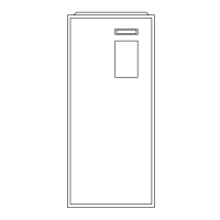
Fig. 27—Typical Heating and Cooling Application Wiring Diagram
A99440
115-V FIELD-
SUPPLIED
DISCONNECT
AUXILIARY
J-BOX
24-V
TERMINAL
BLOCK
THREE-WIRE
HEATING-ONLY
FIVE WIRE
NOTE 1
NOTE 2
FIELD-SUPPLIED
DISCONNECT
CONDENSING
UNIT
TWO
WIRE
FURNACE
C
O
N
T
R
O
L
R
G
COM
WCR GY
GND
GND
FIELD 24-V WIRING
FIELD 115-, 208/230-, 460-V WIRING
FACTORY 24-V WIRING
FACTORY 115-V WIRING
208/230- OR
460-V
THREE
PHASE
208/230-V
SINGLE
PHASE
BLOWER DOOR SWITCH
WHT
BLK
WHT
BLK
NOTES: Connect Y-terminal in furnace as shown for proper blower operation.
Some thermostats require a "C" terminal connection as shown.
If any of the original wire, as supplied, must be replaced, use
same type or equivalent wire.
W
Y/Y2
GND
THERMOSTAT
TERMINALS
1.
2.
3.
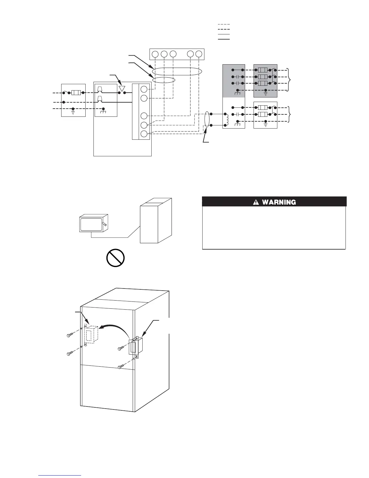
Fig. 28—Disconnect Switch and Furnace
A93033
COPPER
WIRE ONLY
ELECTRIC
DISCONNECT
SWITCH
ALUMINUM
WIRE
Fig. 29—Relocating J-Box
A00212
FACTORY
INSTALLED
LOCATION
ALTERNATE
FIELD
LOCATION
21
→
 Loading...