Unit must not be installed, operated, and then turned off and
left in an unoccupied structure during cold weather when
temperature drops to 32°F and below unless drain trap and
drain line have adequate freeze protection. See Service and
Maintenance Instructions for winterizing procedure. (See Fig.
15.) Failure to follow this caution will result in intermittent
unit operation.
Step 10—Condensate Drain
GENERAL
Condensate trap is shipped installed in the blower shelf and factory
connected for UPFLOW applications. Condensate trap must be
RELOCATED for use in DOWNFLOW and HORIZONTAL
applications.
Condensate trap MUST be used for all applications.
An external trap is not required when connecting the field drain to
this condensate trap.
The field drain connection (condensate trap or drain tube coupling)
is sized for l/2-in. CPVC, 1/2-in. PVC, or 5/8-in. ID tube
connection.
Drain pipe and fittings must conform to ANSI standards and
ASTM D1785, D2466 or D2846. CPVC or PVC cement must
conform to ASTM D2564 or F493. Primer must conform to ASTM
F656. In Canada, use CSA or ULC listed schedule 40 CPVC or
PVC drain pipe, fittings, and cement.
When a condensate pump is required, select a pump which is
approved for condensing furnace applications. To avoid conden-
sate spillage, select a pump with an overflow switch.
Furnace condensate is mildly acidic, typically in the pH range of
3.2 to 4.5. Due to corrosive nature of this condensate, a condensate
pH neutralizing filter may be desired. Check with local authorities
to determine if a pH neutralizer is required.
APPLICATION
The furnace, A/C, and humidifier drains may be combined and
drained together. The A/C drain must have an external, field-
supplied trap prior to the furnace drain connection. All drain
connections (furnace, A/C, or humidifier) must be terminated into
an open or vented drain as close to the respective equipment as
possible to prevent siphoning of the equipment’s drain.
See Fig. 46 for example of possible field drain attachment using
1/2-in. CPVC or PVC tee for vent and A/C or humidifier drain
connection.
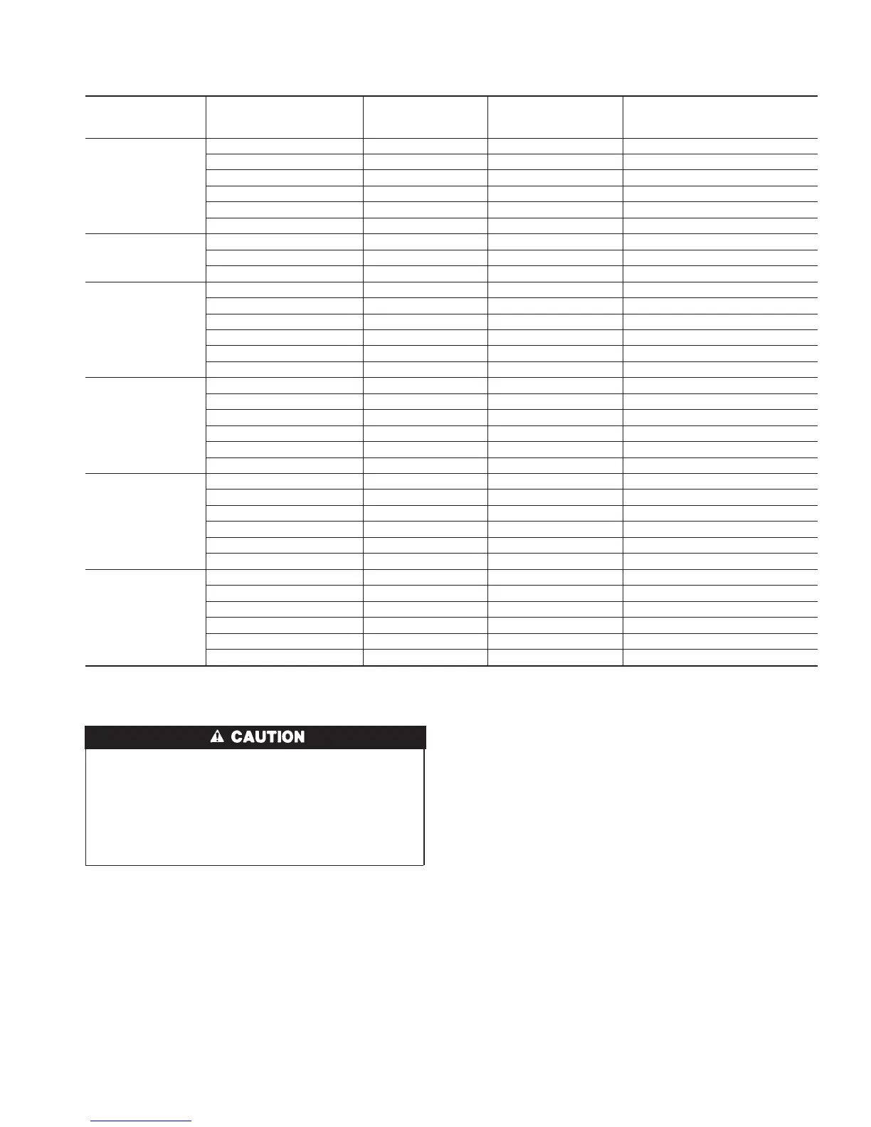
Table 8—Maximum Allowable Exposed Vent Pipe Length (ft) With and Without Insulation in Winter Design
Temperature Ambient*
FURNACE
SIZE
WINTER DESIGN
TEMPERATURE
(°F)
MAX PIPE
DIAMETER
(IN.)
WITHOUT
INSULATION
WITH 3/8–IN. OR
THICKER INSULATION†
040
20 1.5 51 70
0 1.5 28 70
-20 1.5 16 70
20 2 45 70
0 2 22 70
-20 2 10 58
060
20 2 65 70
0 2 35 70
-20 2 20 70
080
20 2 55 55
0 2 48 55
-20 2 30 55
20 2.5 70 70
0 2.5 47 70
-20 2.5 28 70
100
20 2.5 40 40
0 2.5 40 40
-20 2.5 38 40
20 3 70 70
0 3 50 70
-20 3 28 70
120
20 3 70 70
0 3 61 70
-20 3 37 70
20 4 70 70
0 4 48 70
-20 4 23 70
140
20 3 60 60
0 3 60 60
-20 3 44 60
20 4 70 70
0 4 57 70
-20 4 30 70
* Pipe length (ft) specified for maximum pipe lengths located in unconditioned spaces. Pipes located in unconditioned space cannot exceed total allowable pipe length
as specified in Table 7.
† Insulation thickness based on R value of 3.5 per in.
33
→
 Loading...