HEATING MODE
(See Fig. 27 for thermostat connections.)
The wall thermostat ″calls for heat,″ closing the R to W
circuit. The furnace control performs a self-check, verifies the
pressure switch contacts PRS are open, and starts the inducer
motor IDM.
a. Inducer Prepurge Period- As the inducer motor IDM
comes up to speed, the pressure switch contacts PRS close
to begin a 15-second prepurge period.
b. Igniter Warm-Up- At the end of the prepurge period, the
Hot-Surface igniter HSI is energized for a 17-second
igniter warm-up period.
c. Trial-for-Ignition Sequence- When the igniter warm-up
period is completed the main gas valve relay contacts
GVR-1 and -2 close to energize the gas valve GV, the gas
valve opens, and 24 vac power is supplied for a field-
installed humidifier at the HUM terminal. The gas valve
GV permits gas flow to the burners where it is ignited by
the Hot Surface Igniter HSI. Five seconds after the GVR-1
closes, a 2-second flame period begins. The HSI igniter
will remain energized until the flame is sensed or until the
2-second flame proving period begins.
d. Flame-Proving- When the burner flame is proved at the
flame-proving sensor electrode FSE, the furnace control
CPU begins the blower-ON delay period and continues to
hold the gas valve GV open. If the burner flame is not
proved within two seconds, the control CPU will close the
gas valve GV, and the control CPU will repeat the ignition
sequence for up to three more Trials-For-Ignition before
going to Ignition-Lockout. Lockout will be reset auto-
matically after three hours, or by momentarily interrupting
115 vac power to the furnace, or by interrupting 24 vac
power at SEC1 or SEC2 to the furnace control CPU (not at
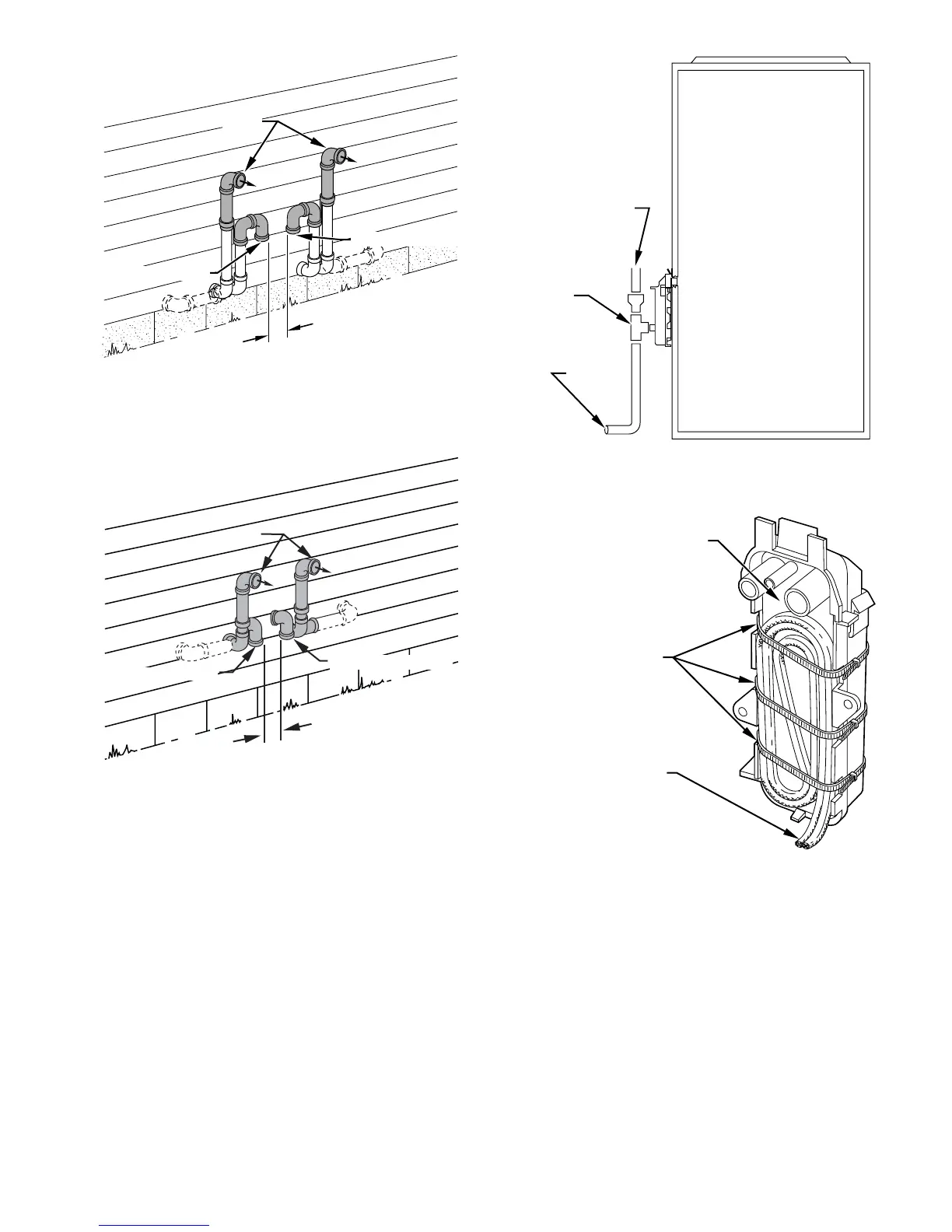
Fig. 44—Raised Sidewall Termination When Wall
Penetration is 12 in. or Less Above Snow or Grade
(Dimension “A” is Touching or 2-in. Maximum
Separation)
A96129
A
COMBUSTION AIR
COMBUSTION AIR
VENT
Fig. 45—Sidewall Termination of More than 12 in.
(Dimension “A” is Touching or 2-in. Maximum
Separation)
A96130
COMBUSTION AIR
OMBUSTION AIR
VENT
A
Fig. 46—Example of Field Drain Attachment
A94054
OPEN STAND
PIPE FOR
A/C OR
HUMIDIFIER
DRAIN
TEE
TO OPEN
DRAIN
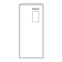
Fig. 47—Condensate Trap Heat Tape
A93036
CONDENSATE TRAP
WIRE TIE(S)
HEAT TAPE
(3 WRAPS MINIMUM)
35
→