Step 8—Electrical Connections
See Fig. 27 for field wiring diagram showing typical field 115-v
and 24-v wiring. Check all factory and field electrical connections
for tightness.
Field-supplied wiring shall conform with the limitations of 63°F
(33°C) rise.
Blower access door switch opens 115-v power to control. No
component operation can occur. Do not bypass or close
switch with panel removed. Failure to follow this warning
could result in personal injury or death.
Furnace control must be grounded for proper operation or
control will lock out. Control is grounded through
green/yellow wire connected to gas valve and burner box
screw. Failure to follow this caution will result in intermittent
unit operation.
115–V WIRING
Before proceeding with electrical connections, make certain that
voltage, frequency, and phase correspond to that specified on
furnace rating plate. Also, check to be sure that service provided
by power supply is sufficient to handle load imposed by this
equipment. Refer to rating plate or Table 4 for equipment electrical
specifications. Make all electrical connections in accordance with
National Electrical Code (NEC) ANSI/NFPA 70-2002 and any
local codes or ordinances that might apply. For Canadian instal-
lations, all electrical connections must be made in accordance with
Canadian Electrical Code CSA C22.1 or authorities having juris-
diction. Use a separate, branch electrical circuit containing a
properly sized fuse or circuit breaker for this furnace. See Table 4
for wire size and fuse specifications. A disconnecting means must
be located within sight from and readily accessible to furnace.
NOTE: Proper polarity must be maintained for 115-v wiring. If
polarity is incorrect, control LED status indicator will flash rapidly
and furnace will NOT operate.
Do not connect aluminum wire between disconnect switch
and furnace. Use only copper wire. (See Fig. 28.) Failure to
follow this caution will result in minor unit operation or
performance satisfaction.
The cabinet MUST have an uninterrupted or unbroken ground
according to NEC ANSI/NFPA 70-2002 and Canadian Elec-
trical Code CSA C22.1 or local codes to minimize personal
injury if an electrical fault should occur. This may consist of
electrical wire or conduit approved for electrical ground when
installed in accordance with existing electrical codes. Do not
use gas piping as an electrical ground. Failure to follow this
warning could result in electrical shock, fire, or death.
J-Box Relocation
1. Remove 2 screws holding auxiliary J-box. (See Fig. 29.)
2. Rotate J-box 180° and attach box to left side, using holes
provided.
If manual disconnect switch is to be mounted on furnace,
select a location where a drill or fastener will not contact
electrical or gas components. Failure to follow this caution
will result in intermittent unit operation or performance
satisfaction.
24–V WIRING
Connect 24-v thermostat leads to 24-v terminal block on furnace
control. For proper cooling operation, Y wire from thermostat
MUST be connected to Y/Y2 terminal on furnace control, as
shown in Fig. 27. The 24-v terminal block is marked for easy
connection of field wiring. (See Fig. 30.) The 24-v circuit contains
a 3-amp, automotive-type fuse located on furnace control. (See
Fig. 31.) Any electrical shorts of 24-v wiring during installation,
service, or maintenance may cause fuse to blow. If fuse replace-
ment is required, use only a fuse of identical size (3 amp) and type.
The control will flash code 24 when fuse needs replacement.
NOTE: Use AWG No. 18 color-coded copper thermostat wire
for lengths up to 100 ft. For wire lengths over 100 ft, use AWG No.
16 wire.
ACCESSORIES
1. Electronic Air Cleaner (EAC)
Two quick-connect terminals marked EAC-1 and EAC-2 are
provided for EAC connection. (See Fig. 31.) These terminals
are energized with 115-v (1.0-amp maximum) during blower
motor operation.
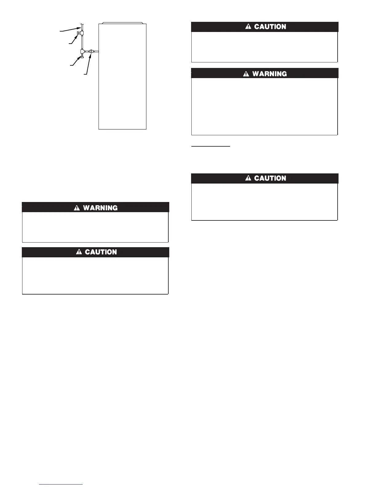
Fig. 26—Typical Gas Pipe Arrangement
A93324
UNION
SEDIMENT
TRAP
MANUAL
SHUTOFF
VALVE
(REQUIRED)
GAS
SUPPLY
20
→
→
→
 Loading...