Concentric Vent/Air Termination Kit
1. Determine location for termination.
Consideration of the following should be made when deter-
mining an appropriate location for termination kit.
a. Comply with all clearance requirements as stated in Table
5.
b. Termination kit should be positioned where vent vapors
will not damage plants/shrubs or air conditioning equip-
ment.
c. Termination kit should be positioned so it will not be
affected by wind eddy (such as inside building comers) or
that may allow recirculation of flue gases, airborne leaves,
or light snow.
d. Termination kit should be positioned where it will not be
damaged by or subjected to foreign objects, such as stones,
balls, etc.
e. Termination kit should be positioned where vent vapors are
not objectionable.
2. Cut one 4-in. diameter hole for 2-in. kit, or one 5-in. diameter
hole for 3-in. kit.
3. Loosely assemble concentric vent/air termination components
together using instructions in kit.
4. Slide assembled kit with rain shield REMOVED through hole.
NOTE: Do not allow insulation or other materials to accumulate
inside of pipe assembly when installing it through hole.
Roof terminations—Locate assembly through roof to appropriate
height as shown in Fig. 37.
Sidewall terminations—Locate assembly through sidewall with
rain shield positioned no more than 1-in. from wall as shown in
Fig. 38.
5. Disassemble loose pipe fittings. Clean and cement using same
procedures as used for system piping.
6. Check required dimensions as shown in Fig. 37 or 38.
MULTIVENTING AND VENT TERMINATIONS
When 2 or more 58MXA Furnaces are vented near each other,
each furnace must be individually vented. NEVER common vent
or breach vent 58MXA furnaces. When 2 or more 58MXA
furnaces are vented near each other, 2 vent terminations may be
installed as shown in Fig. 41, 42, 43, 44, and 45, but next vent
termination must be at least 36 in. away from first 2 terminations.
It is important that vent terminations be made as shown to avoid
recirculation of flue gases. Dimension ″A″ in Fig. 41, 42, 43, 44,
and 45 represents distance between pipes or rain shields, as
touching or 2-in. maximum separation.
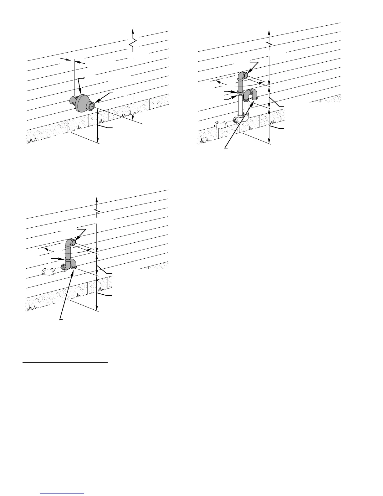
Fig. 38—Concentric Vent and Combustion-Air Side
Termination
A93055
MAINTAIN 12 IN.
CLEARANCE
ABOVE HIGHEST
ANTICIPATED SNOW
LEVEL OR GRADE,
WHICHEVER IS
GREATER.
COMBUSTION-AIR
VENT
1″ MAXIMUM
12″ MINIMUM
OVERHANG OR ROOF
Fig. 39—Sidewall Termination of 12 in. or More
A87225
MAINTAIN 12 IN.
CLEARANCE
ABOVE HIGHEST
ANTICIPATED SNOW
LEVEL OR GRADE,
WHICHEVER IS
GREATER.
90°
VENT
12 IN. SEPARATION
BETWEEN BOTTOM OF
COMBUSTION AIR AND
BOTTOM OF VENT
BRACKET
COMBUSTION-AIR
12″ MINIMUM
OVERHANG OR ROOF
Fig. 40—Sidewall Termination When Wall Penetra-
tion is Less than 12 in Above Snow or Grade.
A87226
MAINTAIN 12 IN.
CLEARANCE
ABOVE HIGHEST
ANTICIPATED SNOW
LEVEL OR GRADE,
WHICHEVER IS
GREATER.
90°
VENT
12 IN. SEPARATION
BETWEEN BOTTOM OF
COMBUSTION AIR AND
BOTTOM OF VENT
BRACKET
COUPLING
12″ MINIMUM
OVERHANG OR ROOF
COMBUSTION-AIR
(ELBOW PARALLEL
TO WALL)
32
 Loading...