SUPPLY AIR CONNECTIONS
Upflow Furnaces
Connect supply-air duct to 3/4-in. flange on furnace supply-air
outlet. The supply-air duct attachment must be connected to
ONLY furnace supply-/outlet-air duct flanges or air conditioning
coil casing (when used). DO NOT cut main furnace casing to
attach supply side air duct, humidifier, or other accessories. All
accessories MUST be connected external to furnace main casing.
Downflow Furnaces
Connect supply-air duct to supply-air opening on furnace. The
supply-air duct attachment must be connected to ONLY furnace
supply/outlet or air conditioning coil casing (when used), when
installed on non-combustible material. When installed on combus-
tible material, supply-air duct attachment must be connected to
ONLY an accessory subbase or factory approved air conditioning
coil casing. DO NOT cut main furnace casing to attach supply side
air duct, humidifier, or other accessories. All accessories MUST be
connected external to furnace main casing. Supply air opening duct
flanges must be modified per Fig. 21.
Horizontal Furnaces
Connect supply-air duct to supply air opening on furnace. The
supply-air duct attachment must be connected to ONLY furnace
supply/outlet or air conditioning coil casing (when used). DO NOT
cut main furnace casing to attach supply side air duct, humidifier,
or other accessories. All accessories MUST be connected external
to furnace main casing.
RETURN AIR CONNECTIONS
The furnace and its return air system shall be designed and
installed so that negative pressure created by the air circulating fan
cannot affect another appliance’s combustion air supply or act to
mix products of combustion with circulating air. The air circulat-
ing fan of the furnace, if installed in an enclosure communicating
with another fuel-burning appliance not of the direct-vent type,
shall be operable only when any door or panel covering an opening
in the furnace fan compartment or in a return air plenum on ducts
is in the closed position.
Never connect return-air ducts to the back of the furnace.
Return-air duct connections on furnace side(s) permitted in
upflow applications only. A failure to follow this warning
could result in fire, personal injury, or death.
Upflow Furnaces
The return-air duct must be connected to bottom, sides (left or
right), or a combination of bottom and side(s) of main furnace
casing as shown in Fig. 2 Bypass humidifier may be attached into
unused side return air portion of the furnace casing. DO NOT
connect any portion of return-air duct to back of furnace casing.
Downflow and Horizontal Furnaces
The return-air duct must be connected to end inlet opening
provided as shown in Fig. 2. DO NOT cut into casing sides or back
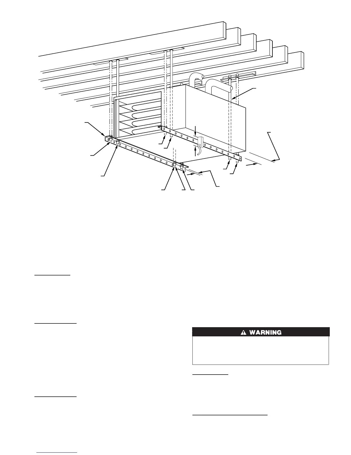
Fig. 22—Crawlspace Horizontal Application
A93304
NOTES:
ANGLE
IRON OR
EQUIVALENT
(B)
(A) ROD LOCATION
USING DIMPLE
LOCATORS
(SEE DIMENSIONAL
DWG FOR
LOCATIONS)
13
/16-IN. MAX
ALTERNATE SUPPORT
LOCATION FROM BACK
ALTERNATE SUPPORT
LOCATION 4-IN. MIN
8-IN. MAX
3
⁄8-IN. ROD
(A)
(B)
(A)
(B)
(B)
(A)
1. A 1 In. clearance minimum between top of
furnace and combustible material.
2. The entire length of furnace must be
supported when furnace is used in horizontal
position to ensure proper drainage.
(A) PREFERRED ROD LOCATION
(B) ALTERNATE ROD LOCATION
DRAIN
5
3
⁄
4
″
3
/8-IN. HEX NUT
& WASHER (4)
REQD PER ROD
17

 Loading...