b. Install removed clamp and plug into UPPER collector box
drain tube (blue label) which was previously connected to
condensate trap.
c. Connect LOWER collector box drain tube (blue and white
striped label) to condensate trap. Tube does not need to be
cut.
d. Clamp tube to prevent any condensate leakage.
2. Inducer Housing Drain Tube
a. Remove factory-installed cap and clamp from LOWER
inducer housing drain connection.
b. Remove and discard UPPER (molded) inducer housing
drain tube which was previously connected to condensate
trap.
c. Install cap and clamp on UPPER inducer housing drain
connection where molded drain tube was removed.
d. Use inducer housing drain extension tube (violet label and
factory-supplied in loose parts bag) to connect LOWER
inducer housing drain connection to condensate trap.
e. Determine appropriate length, cut, and connect tube to
condensate trap.
f. Clamp tube to prevent any condensate leakage.
3. Relief Port Tube
Refer to Pressure Switch Tubing section for connection
procedure.
CONDENSATE TRAP FIELD DRAIN ATTACHMENT
Refer to Condensate Drain section for recommendations and
procedures.
PRESSURE SWITCH TUBING
One collector box pressure tube (pink label) is factory connected to
the pressure switch for use when furnace is installed in UPFLOW
applications. This tube MUST be disconnected and used for the
condensate trap relief port tube. The other collector box pressure
tube (green label) which was factory connected to the condensate
trap relief port connection MUST be connected to the pressure
switch in DOWNFLOW or HORIZONTAL RIGHT applications.
NOTE: See Fig. 12 or tube routing label on main furnace door to
check for proper connections.
Relocate tubes as described below.
1. Disconnect collector box pressure tube (pink label) attached to
pressure switch.
2. Extend collector box pressure tube (green label) which was
previously connected to condensate trap relief port connection
by splicing to small diameter tube (factory-supplied in loose
parts bag).
3. Route extended collector box pressure tube behind inducer
motor bracket then between inducer motor and pressure
switch.
4. Connect collector box pressure tube (green label) to pressure
switch connection labeled COLLECTOR BOX.
5. Use remaining smaller diameter tube (factory-supplied in
loose parts bag) to extend collector box pressure tube (pink
label) which was previously connected to pressure switch.
6. Route this extended tube (pink label) to condensate trap relief
port connection.
7. Determine appropriate length, cut, and connect tube.
8. Clamp tube to relief port connection.
CONDENSATE TRAP FREEZE PROTECTION
Refer to Condensate Drain Protection section for recommenda-
tions and procedures.
CONSTRUCT A WORKING PLATFORM
Construct working platform where all required furnace clearances
are met. (See Fig. 3 and 11.)
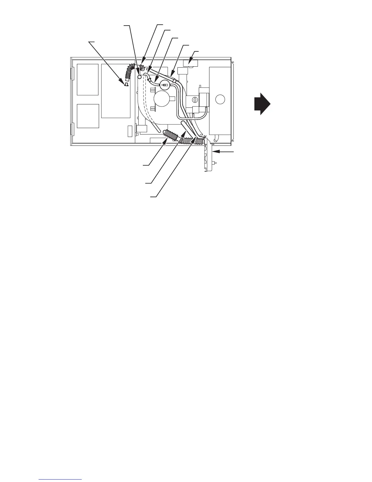
Fig. 12—Horizontal Right Tube Configuration
A00214
PLUG
COLLECTOR BOX DRAIN TUBE
(BLUE AND WHITE STRIPED)
INDUCER HOUSING
DRAIN TUBE (VIOLET)
COLLECTOR BOX
EXTENSION TUBE
COLLECTOR BOX TUBE (GREEN)
CAP
COLLECTOR BOX DRAIN TUBE (BLUE)
COLLECTOR BOX TUBE (PINK)
CONDENSATE
TRAP
COLLECTOR BOX EXTENSION TUBE
AUXILARY “J” BOX RELOCATED HERE
12

 Loading...