20
9. PL7: ABCD comm. stat conn.
19. LED2 STATUS: Status and fault
code light
10. COND:Condensateoverflow
A150170
Fig. 23 -- UPM Board
The UPM Board includes the following features:
SLOW PRESSURE SWITCH: The low pressure switch safety is
designed to shut down the compressor in the event of loss of charge.
Cut in 60 +/-- 15 psig and cut out 40 +/-- psig.
SHIGH PRESSURE SWITCH: The high pressure switch safety is
designed to shut down the compressor if it exceeds limits. Cut in
420 +/-- 15 psig and cut out 600 +/-- psig.
SANTI--SHORT CYCLE TIMER: 5 minute delay on break timer
to prevent compressor short cycling.
SRANDOM S TART: Each board has a unique random start delay
ranging from 30 to 270 seconds on initial power up to reduce the
chance of multiple unit simultaneously starting at the same time after
power up or after a power interruption, thus avoiding creating large
electrical spike.
SLOW PRESSURE BYPASS TIMER:Ifthecompressoris
running and the low pressure switch opens, the board will keep the
compressor ON for 120 seconds. After 2 minutes if the low pressure
switch remains open, the board will shut down the compressor and
enter a soft lockout. The compressor will not be energized until the
low pressure switch closes an d th e an ti --sh o rt cycle time delay
expires. If the low pressure switch opens 2--4 times in 1 hour, the unit
will enter a 4 hour lockout period.
Pressure Switch Protection:
The geothermal unit is equipped
with high-- and low-- pressure switches. If the control senses the
opening of a high -- or low-- pressure switch, it will respond as
follows:
1. De-- energize the compressor contactor.
2. Display the appropriate fault code (see Table 14).
3. After a 15 minute delay, if there is a call for cooling or heat-
ing and LPS or HPS is reset, the compressor contactor is
energized.
4. If the open switch closes anytime after the 15 minute delay,
then resume operation with a call for cooling or heating.
5. If LPS or HPS trips 2--4 consecutive cycles per the dip
switch lockout setting or UI setting (Communicating only),
the unit operation is locked out for 4 hours.
6. In the event of a high--pressure switch trip or high--pressure
lockout, check the refrigerant charge, and the coax coil (in
cooling) for water issues, or indoor airflow in heating.
7. In the event of a low--pressure switch trip or low-- pressure
lockout, check the refrigerant charge and indoor airflow
(cooling) and coax coil water pressure and flow in heating.
SCONTROL FAULT: If the geothermal unit control board has
failed, the control will flash the appropriate fault code (see Table 14).
The control board should be replaced.
SUPM DIP SWITCH SETTINGS: T he UP M h as 3 features
controlled on the dip switch.
1. Freeze Protection Limit for the Freeze one water coil.
2. Lockout Settings (Soft Lockouts)
3. Brownout (High voltage protection)
DIP SWITCH
DIP Switch Position
ON OFF (Default)
SW1
Freeze Protection
Limit
15F 26° F
SW2
Number of Trips
to Lockout
(HPS / LPS)
4 2
SW3 Brownout
Brownout Protec-
tion is Disabled
Brownout Pro-
tection is Active
NOTE: The settings are recommended to be adjusted in the wall
control screens and UPM dipswitch settings left at default
positions.
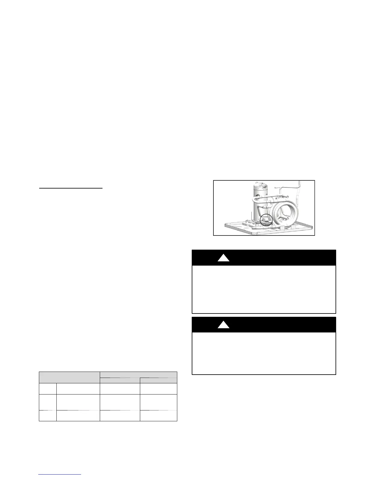
SWATER COIL FREEZE SENSOR: The water coil is protected
by a thermistor located between the condensing water coil (coax)
and the thermal expansion valve (see Fig. 9).
The setting is default at 26_F (-- 3.33_C) but can be changed for units
with ample anti--freeze to have a lower setting of 15_F (--9.44_C)
with the dip switch selection or UI setting.
If the un it is emp loy ing an op en lo op system (no ant i-- freeze
protection), the freeze limit trip for the UI will only allow selection
of 26_F (-- 3.33_C) in order to shut down the unit at the appropriate
leaving water temperature and protect the heat pump from freezing.
If the refrigerant temperature drops below or remains at freezing
limit trip for 30 seconds, the UPM will shut down the compressor
and the board will flash fault code 86 (FRZ1 lockout). Fault code 86
will rem ain until the con d itio n is co rrected an d also requires a
manual reset low voltage circuit. After a manual reset and there is a
call for heating, the unit will be re--energized automatically ONLY
when the freeze sensor temperature is 7_F (-- 13.9_C) above setpoint
(SW1).
Fault code 57 is FRZ1 sensor fault, which means the sensor is
invalid, meaning the sensor could be open or faulty. If the sensor is
invalid or out of the range (the range is from -- 50 _F to 150 _F
(--45.6 _C to 65.6_C), the compresso r will be de --en ergized and
display the freeze sensor fault code (57). When the sensor goes back
into range, freeze sensor fault code will clear and the system will start
up automatically if a demand exists.
For troubleshooting the Water Coil Freeze Sensor, refer to Table
14.
A14121
Fig. 24 -- Freeze Pr otection Sensor Location
CAUTION
!
UNIT DAMAGE AND/OR OPERATION HAZARD
Failure to follow this caution may result in unit damage
and/or improper equipment operation.
If unit is employing a fresh water system (no anti--freeze
protection), it is extremely important to have the Freeze1
set to the default 26_F (--3.33_C).
CAUTION
!
UNIT DAMAGE AND/OR OPERATION HAZARD
Failure to follow this caution may result in unit damage
and/or improper equipment operation.
Freeze sensor will not guard against the loss of water. A
flow switch is recommended to prevent the unit from
running if water flow is lost or reduced.
 Loading...