21
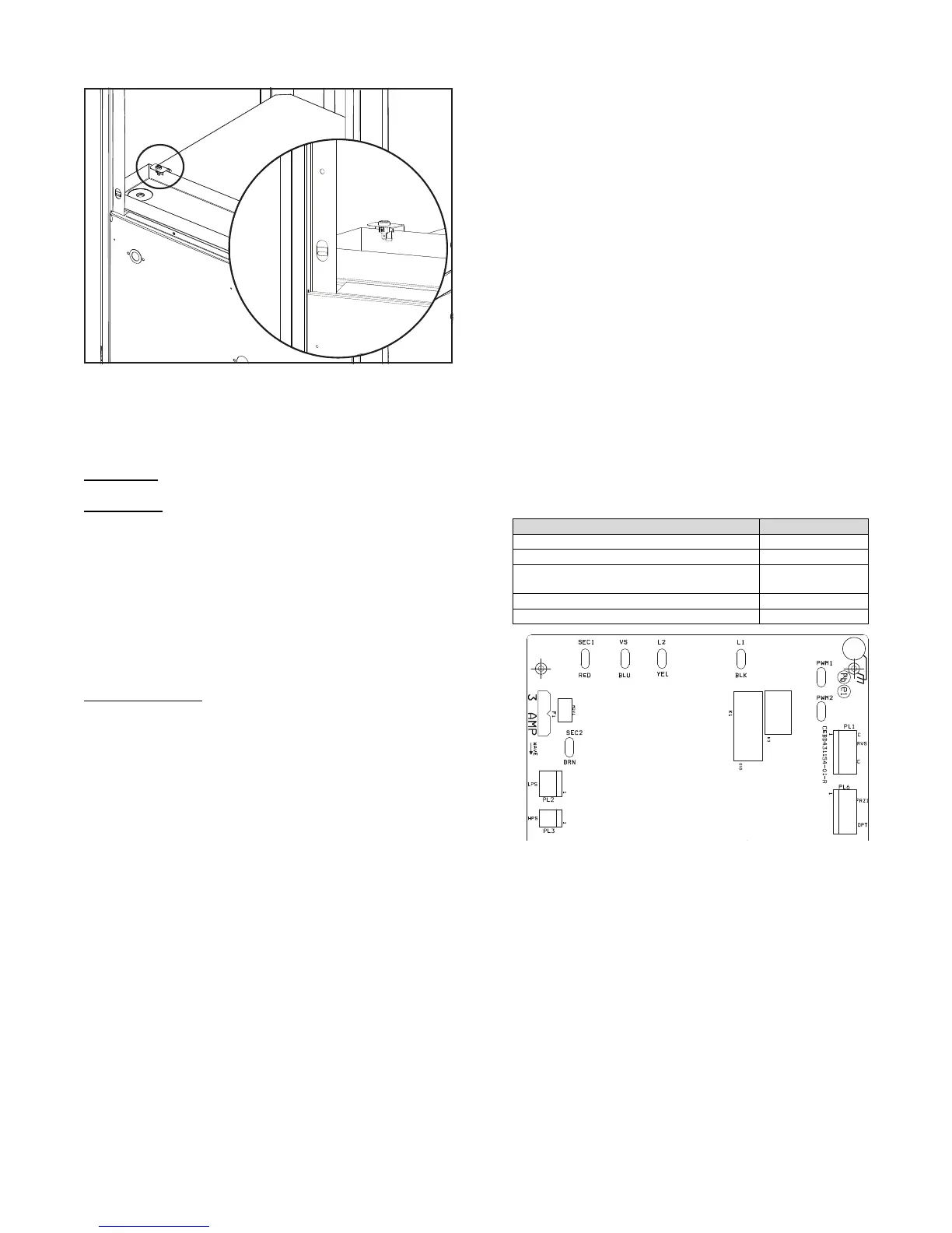
SCONDENSATE OVERFLOW PROTECTION SENSOR:
Located in the drain p an of the un it and connected to the ”COND”
terminal on the UPM board. See Fig. 25.
A14123
Fig. 25 -- Condensate Overflow Protection Sensor Location
SLOCKOUTS: If system protection faults occur, the unit will shut
down the compressor and fault codes will be shown on the UPM
board and the UI screen.
There are two types of lockouts:
Soft lockouts
-- This is a selectable dipswitch position to allow 2 or 4
unit trips before going to hard lockout.
Hard lockouts
-- Will require a manual reset.
This applies to all unit trips unless otherwise noted. In order to exit
the hard lockout early for servicing, the low voltage power to the
unit would need to be reset and the fault conditions corrected.
NOTE: The blower motor will remain active during a lockout
condition.
SBROWNOUT PROTECTION: The compressor will be shut
down if the incoming voltage falls below 170 VAC for 4 seconds
and fau lt co de will d isplay o n UP M L ED and w all con trol (if
applicable). The compressor will remain off until the voltage is
above 173 VAC for at least 4 seconds and the anti--short cycle timer
times out.
Defeat the Brownout
-- The high voltage brownout feature can be
defeated in the event of nuisance trips due to severe noisy power
conditions. The UPM dip switch has brownout ON as default, to
defeat the brown out protection, the selection can be changed to
OFF. All efforts should be exhausted to correct any electrical
deficiencies before defeating this safety feature to eliminate possible
equipment damage.
S230V LINE (POWER DISCONNECT) DETECTION:Ifthereis
no 230V at the compressor contactor(s) when the indoor unit is
powered and cooling or heating demand exists, the appropriate fault
code is displayed. Verify the disconnect is closed and 230V wiring
is connected to the unit.
SCOMPRESSOR VOLTAGE SENSING: The control board input
termin als lab eled V S and L 2 (see F ig. 23) are u sed to detect
compressor voltage status and alert the user of potential problems.
The control continuously monitors the high voltage on the run
capacitor of the compressor motor. Voltage should be present any
time the compressor contactor is energized and voltage should not be
present when the contactor is de-- energized.
SCONTACTOR SHORTED DETECTION: If there is compressor
voltage sensed when there is no demand for compressor operation,
the contactor may be stuck closed or there may be a wiring error. The
control will flash the appropriate fault code.
If the control senses the compressor voltage after start--up and is then
absent for 10 consecutive seconds while cooling or heating demand
exists, the thermal protector is open.
The control de--energizes the compressor contactor for 15 minutes.
The control Status LED will flash the appropriate code shown in
Table 14. After 15 minutes, with a call for low or high stage cooling
or heating, the compressor contactor is energized. If the call for
coo ling o r h eating co ntin ues, th e co ntro l w ill energize the
compressor contactor every 15 minutes. If the thermal protector
closes, (at the next 15 minute interval check) the unit will resume
operation. If the thermal protector trips for three consecutive cycles,
then unit operation is locked out for 4 hours and the appropriate fault
code is displayed.
SNO 230V AT COMPRESSOR CONTACTOR: If the compressor
voltage is not sensed when the compressor should be starting, the
appropriate contactor may be stuck open or there is a wiring error.
The control will flash the appropriate fault code. Check the contactor
and control box wiring. Refer to Table 8 and Fig. 26.
Table 8 – UPM Voltage Detection
UPM Voltage Detection Fault Code
Brownout L1 and L2 46
Compressor voltage sensing VS and L1 74
230V line power disconnect detection on L1
and L2
47
Contactor shorted detection VS and L1 73
24V transformer Sec 1 an d Sec 2 No fa ults
Fig. 26 -- UPM Board
L1, L2, VS, SEC 1 and SEC 2 Locations
 Loading...