42
Counter--Flow Configuration
The Counter--Flow Configuration water source heat pump is a
dedicated down flow configuration. Available from the factory in
Left --hand and right hand return air configurations.
Vertical Configuration (Top Discharge)
Vertical top discharge units where the blower housing is attached to
the top panel are field convertible from left return to right return
OR from right return to left return.
To convert a left hand return unit to a right hand return unit (or vice
versa), the following items need to be completed or relocated:
S Remove front and back panels (upper and lower).
S Relocate electrical box to same position in opposite side.
S Relocate the condensate drain location to opposite side utilizing
the existing knock--out.
S Relocate HRP (hot water pump switch) to opposite side using
the existing knock--out.
S Rotate the unit 180 degrees on its base so the electrical box,
condensate drain and HRP switch are positioned to the new
front.
S Install (optional) auxiliary heat from the new front
S Reinstall the panels so that the upper panel with the badge and
the lower panel with the unit data plate are on the “new” front.
Reinstall the blank panels on the new back.
See Figures below for additional details.
NOTE: Previously, vertical top discharge units were manufactured
with the blower housing mounted to a side bracket on the unit,
allowing the ability to change the return from left or right (or vice
versa) and the supply from top to side or back. Units built with the
blower housing attached to the top panel cannot be re-- configured
for back or side discharge.
NOTE: Blower E--box and panel configuration changes should be
done prior to unit being installed in the final location.
NOTE: All heat pumps are supplied with panel belt which needs
to be removed to access screws for panel removal. The panels have
additional internal fasteners to prevent any air leakage.
!
WARNING
PERSONAL INJURY HAZARD
Failure to follow this caution may result in personal injury.
At least two people are required to perform this operation.
REQUIRED TOOLS:
S 5/16” hex head screwdriver S Phillips head screwdriver
S 3/8” hex head screwdriver S 1/4” hex head screwdriver
S 7/16” hex head screwdriver S Needle nose pliers
S Flat screwdriver
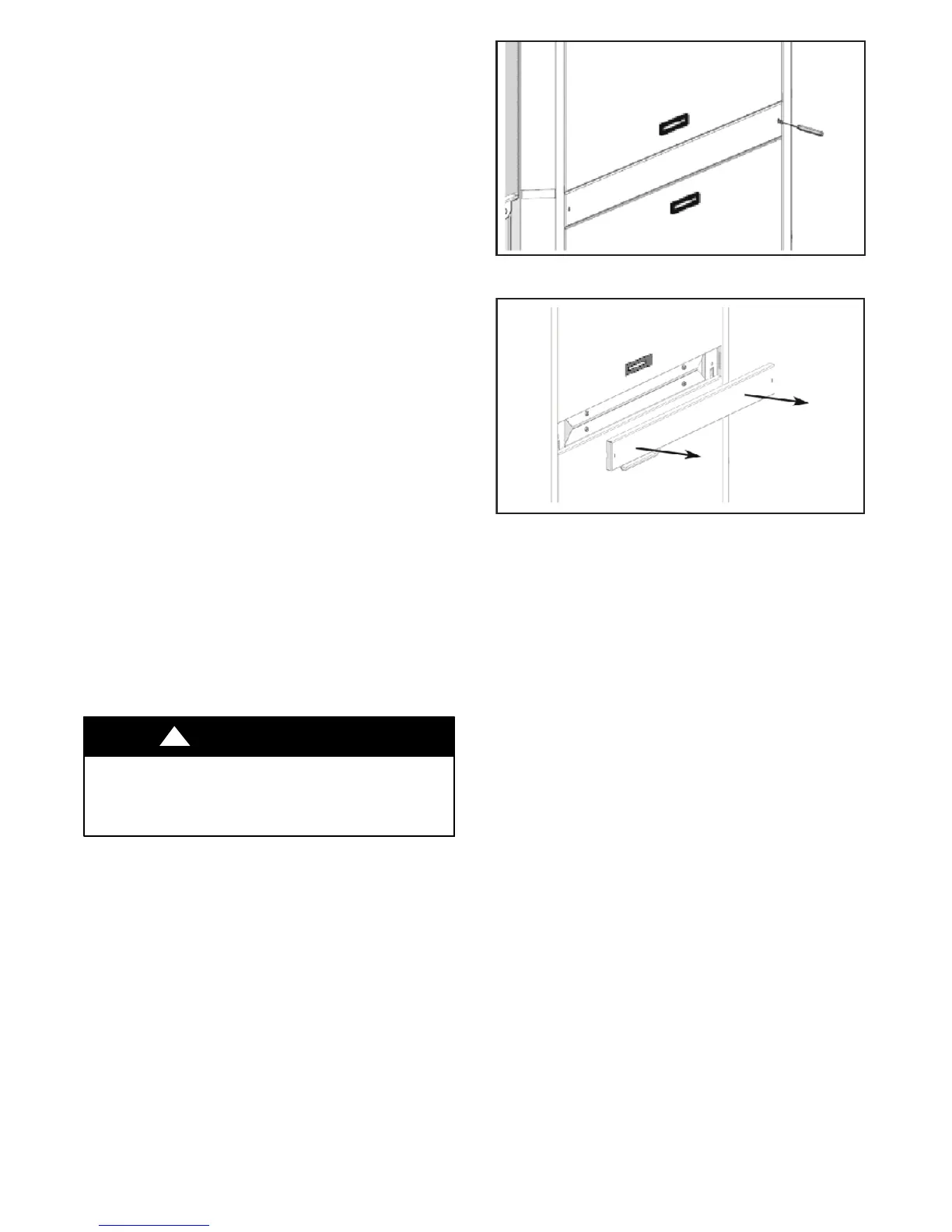
Access to Internal Components
1. Using a Phillips--head screw driver, remove the two (2)
screws.
A14070
Fig. 30 -- Remove Panel Belt
A14071
Fig. 31 -- Remove Panel Belt
 Loading...