43
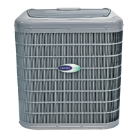
2. Remove and retain Compressor Section access panels
(bottom panel) by removing (3) screws. See Fig. 32.
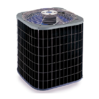
3. Remove and retain Air Handler panel by lifting up and out
as shown in Fig. 33.
A14072
Fig. 32 -- Remove Condensing Section Access Panels
1) UP
2) AWAY
1) UP
2) AWAY
A14074
Fig. 33 -- Remove Air Handler Panel
Condensate Drain Connection Re--Configu ration
When re--configuring the unit from Left-- Hand Return to
Right-- Hand Return, it is necessary to relocate condensate drain
connection from FRONT left corner post to BACK left corner
post. See Fig. 34.
A14090
Fig. 34 -- Relocate Condensate Drain Connection
(front left corner to back left corner)
1. Cut the condensate drain hose on the inside of the cabinet.
NOTE: Be sure to retain the spring.
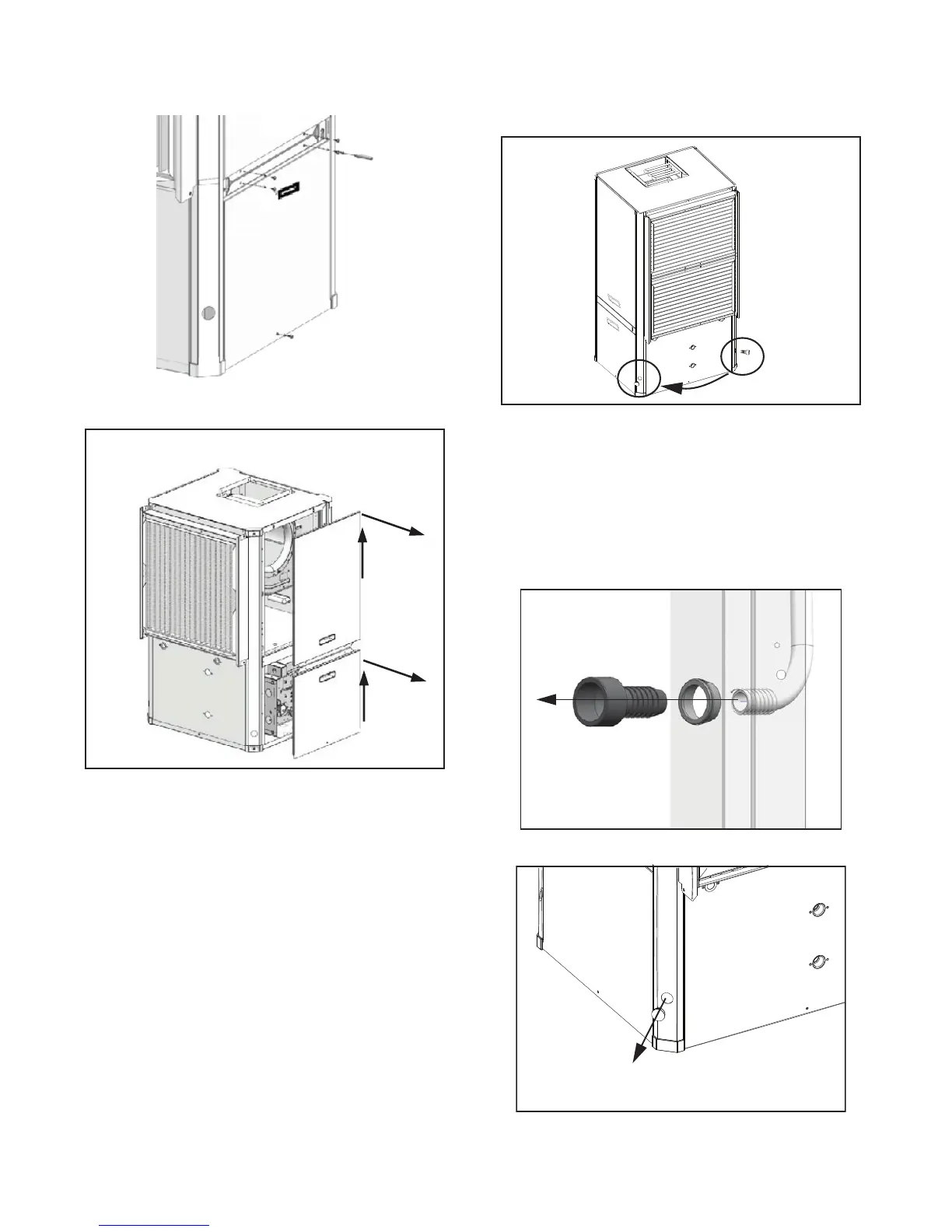
2. Remove and retain condensate drain plastic fitting and
grommet from the hose by pulling it away from the hose
(barb style connection). See Fig. 35.
3. Locate the BACK left condensate drain and remove and
retain plastic plug covering the cutout. See Fig. 36.
A14091
Fig. 35 -- Relocate Condensate Drain Connection
A14092
Fig. 36 -- Relocate Condensate Drain Connection
 Loading...