11
Install Analog Sensors
SUPPLY AIR SENSOR (SAT)
The factory supplies the discharge (supply) air sensor with the
unit and is pre-wired.
OUTDOOR AIR SENSOR (OAT)
The OAT is supplied with the economizer option or accessory.
It is wired through the 12-pin plug (PL6) in the return air sec-
tion of the unit and is mounted on the economizer assembly.
SPACE TEMPERATURE SENSOR (SPT)
There are 2 types of space temperature sensors available from
Carrier, resistive input non-communicating (T55, T56, and
T59) and Rnet communicating (ZS-CAR, ZS-C-CAR,
ZS-H-CAR, ZS-HC-CAR, ZSPL-C-CAR, ZSPL-H-CAR,
ZSPL-HC-CAR, ZSP-CAR, ZSP-C-CAR, ZSP-H-CAR,
ZSP-HC-CAR) sensors. Each type has a variety of options
consisting of: timed override button, set point adjustment, a
LCD screen, combination of humidity or CO
2
sensing and
communication tie in. Space temperature can be also be written
to from a building network or zoning system. However, it is
still recommended that return air duct sensor be installed to al-
low stand-alone operation for back-up. Refer to the configura-
tion section for details on controller configurations associated
with space sensors.
Resistive Non-Communicating Sensor Wiring
For sensor with setpoint adjustment up to 1000 ft (305m), use
three-conductor shielded cable 20 gauge wire to connect the
sensor to the controller. For non set point adjustment (slidebar)
or return air duct sensor, an unshielded, 18 or 20 gauge, two-
conductor, twisted pair cable may be used. Below is the list of
the connections of the SPT to the RTU Open controller, refer to
Fig. 8 and 9 for typical connections at the sensor.
• J20-1 = temperature sensor input (SEN)
• J20-2 = sensor common
• J20-3 = Setpoint adjustment input (SET)
NOTE: See Fig. 10 for space temperature sensor averaging.
T55/56 Override button will no longer function when sensors are
averaged. Only Sensor 1 T56 STO input can be used.
Rnet Communicating Sensor Wiring
The Rnet bus allows local communication with the RTU Open
controller, including communicating sensors. The Rnet bus can
hold up to 6 devices in the following combinations wired in
daisy-chain or hybrid configuration:
• 1-4 ZS-CAR sensor(s)
• 1 ZSPL-CAR or ZSP-CAR sensor
• 1-4 SPS sensor(s), and 1ZSPL-CAR or ZSP-CAR sensor
• Any of the above combinations, plus CO
2
or RH combination
NOTE: Additional ZS sensors must be addressed. Use the jump-
ers on the ZS sensor's circuit board and refer to the sensor installa-
tion instructions for addressing.
For Rnet wiring up to 500ft (152m), use 18 AWG 4 conductor
unshielded plenum rated cable. The RTU Open controller
J13-RNET connection has a 4 pin PCB connector wired as de-
scribed below, Fig. 11 shows sensor Rnet wiring.
• RNET - 1 = Signal ground (GND)
• RNET - 2 = Signal (Rnet+)
• RNET - 3 = Signal (Rnet-)
• RNET - 4 = Power (+12v)
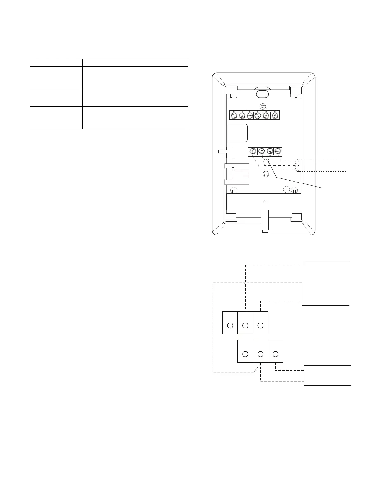
Fig. 8 — Space Temperature Sensor Typical Wiring
(33ZCT56SPT)
Fig. 9 — Space Temperature Sensor Typical Wiring
(33ZCT59SPT)
SENSOR AVERAGING
Non-communicating sensors:
See Fig. 10 for space temperature sensor averaging configura-
tions, only combinations of 4 or 9 sensors will operate correctly.
NOTE: T55/T56 Override button will no longer function when
sensors are averaged. Only 1 T56 STO input can be used. Non-
communication CO
2
sensors can not be averaged.
Unit Size SAT Shipping Location/Installation Location
KC/KCQ 04-06
HC 04-16, HCQ 04-12
LC 04-12
TC 07-16, TCQ 07-14
The SAT is secured to the unit's supply duct
opening. This sensor must be relocated into
the supply duct during unit installation.
HC 17-24
LC 14-26
TC/TCQ 17-30
The SAT is mounted through the side of the
heat chamber below the fan deck, and does
NOT require relocation.
FC 04-07
GC 04-06
FCQ 04-07
GCQ 04-06
The SAT is mounted through the fan deck and
does NOT require relocation.
12345 6
SW1
SEN SET
Cool Warm
BRN (GND)
BLU (SPT)
SENSOR WIRING
JUMPER
TERMINALS
AS SHOWN
BLK
(T56)
OR SET SEN
OPB COM- PWR+
BLU (SPT)
BLK (STO)
24 VAC
SENSOR
WIRING
POWER
WIRING
BRN (COM)
NOTE: Must use a separate isolated transformer.
J20-3
J20-2
J20-1

 Loading...