29
Alarms
Alarms are provided to indicate a possible problem with the
controller or unit. Alarms can be checked through a network
and/or the local access device. All alarms are listed in Table 4
with name, object name, action taken by control, reset method,
and possible cause. Some alarms can occur based on specific
configurations.
SAFETY CHAIN ALARM
This alarm occurs immediately if a field installed, normally
closed, safety contact opens and interrupts 24VAC signal input
#4 (J1-9). The Unit Status will be Shutdown and the System
Mode will be Disable. All unit operations stop immediately
and will not restart until the alarm automatically clears. There
are no configurations for this alarm; it is all based on field in-
stalled wiring. This alarm will not occur if Fire Shutdown
Alarm is active. Normal operation resumes when the safety
chain circuit is complete.
FIRE/SMOKE SHUTDOWN ALARM
This alarm occurs immediately when the smoke detector sens-
es smoke. The Unit Status will be Shutdown and the System
Mode will be Disable. All unit operations stop immediately
and will not restart until the alarm automatically clears. If there
is not a smoke detector installed or the smoke detector did not
trip, check input configurations.
NOTE: The default function for input 5 is a normally open Fire
Shutdown input.
GAS VALVE ALARM
This alarm occurs 60 second after gas heat has been de-ener-
gized but the Integrated Gas Control (IGC) board is still indi-
cating a need for fan operation. Upon alarm detection, the fan
will start immediately and run at its highest speed.
NOTE: The default function for input 9 is a normally open IGC
input for LC WeatherExpert
®
units.
SUPPLY FAN FAILURE
This alarm occurs when the indoor fan is being command on
and the fan status switch feedback is showing the fan off. This
will end current operating mode and disable unit operation.
This alarm requires a fan status switch to be configured on one
of the inputs.
SUPPLY FAN IN HAND
This alarm occurs when the indoor fan is being commanded off
and the fan status switch feedback is showing the fan is on.
This will prevent any operating mode and disable unit opera-
tion. This alarm requires a fan status switch to be configured
on one of the inputs.
COMPRESSOR STATUS
This alarm indicates the base unit's compressor safety circuit is
energized. Cooling, heating, and supply fan outputs are not
interrupted. Normal operation resumes when the compressor
safety circuit is de-energized. This alarm requires field use of
this described compressor safety circuit.
SPACE TEMP SENSOR
This alarm occurs if the space sensor wired to the RTU Open
controller is disconnected or shorted for more than 10 seconds
or if the SPT value from the Network or Airside Linkage is no
longer being received. When this occurs the Unit Status will be
Shutdown and the System Mode will be Run. Sensor, sensor
connections, wiring, board connection, and configurations
should be checked for faults or errors. Alarm will reset auto-
matically when cause is fixed.
ZS SENSOR
This alarm occurs if the ZS sensor wired to the RTU Open con-
troller stops communicating with the controller.
ZS Sensor – This alarm indicates a communication failure of a
connected ZS sensor that previously had been actively commu-
nicating. The alarm is reset when normal ZS sensor communi-
cations resume, if power is cycled to the controller, or if the
Shutdown point is set to Active.
ZS Configuration – This alarm indicates that at least one ZS sen-
sor is configured in the Sensor Binder properties and is not actual-
ly communicating. The alarm is reset when the configured ZS sen-
sor is communicating or the configuration is changed to reflect the
sensor is no longer connected to the Rnet.
SUPPLY AIR TEMP SENSOR
This alarm occurs immediately when the supply air temperature
sensor wired to the RTU Open controller is disconnected or short-
ed. When this occurs the Unit Status will be Shutdown and the
System Mode will be Run. Sensor, sensor connections, wiring,
board connection, and configurations should be checked for faults
or errors. Alarm will reset automatically when cause is fixed.
LOCAL OAT SENSOR
This alarm occurs when the outdoor air sensor indicates a short
or open circuit or the Network OAT value is no longer being
received. Economizer cooling and optimal start functions are
disabled. Normal operation resumes when the controller
detects a valid sensor.
OUTDOOR AIR TEMP SENSOR
This alarm indicates that a valid OAT sensor value is no longer
available to the controller after having been available previously.
Economizer Operation – This alarm is active whenever an econ-
omizer fault is detected as required by California Title 24 Econo-
mizer FDD logic. Once detected, this alarm will stay active until
the Shutdown input is set to Active or the fan is stopped.
Economizer – This point indicates the specific fault detected
and annunciated by the Economizer Operation alarm above.
Detected fault conditions include: Failed to Fully Open, Failed
to Open, Failed to Close, and Stuck Open.
Supply Fan Runtime sfan_rntm_alarm Alert Generated zero the timer Supply fan run time exceeded user
defined limit
Compressor 1 Runtime comp1_rntm_alarm Alert Generated zero the timer Compressor #1 run time limit is
exceeded
Compressor 2 Runtime comp2_rntm_alarm Alert Generated zero the timer Compressor #2 run time limit is
exceeded
Filter filter_alarm Alert Generated Automatic / reset
timer
Dirty Filter, supply fan run time
exceeded, filter switch configuration
wrong.
Airside Linkage Alarm air_linkage_fail Alert Generated Automatic Airside Linkage communication from
VVT
®
master terminal has stopped or
failed
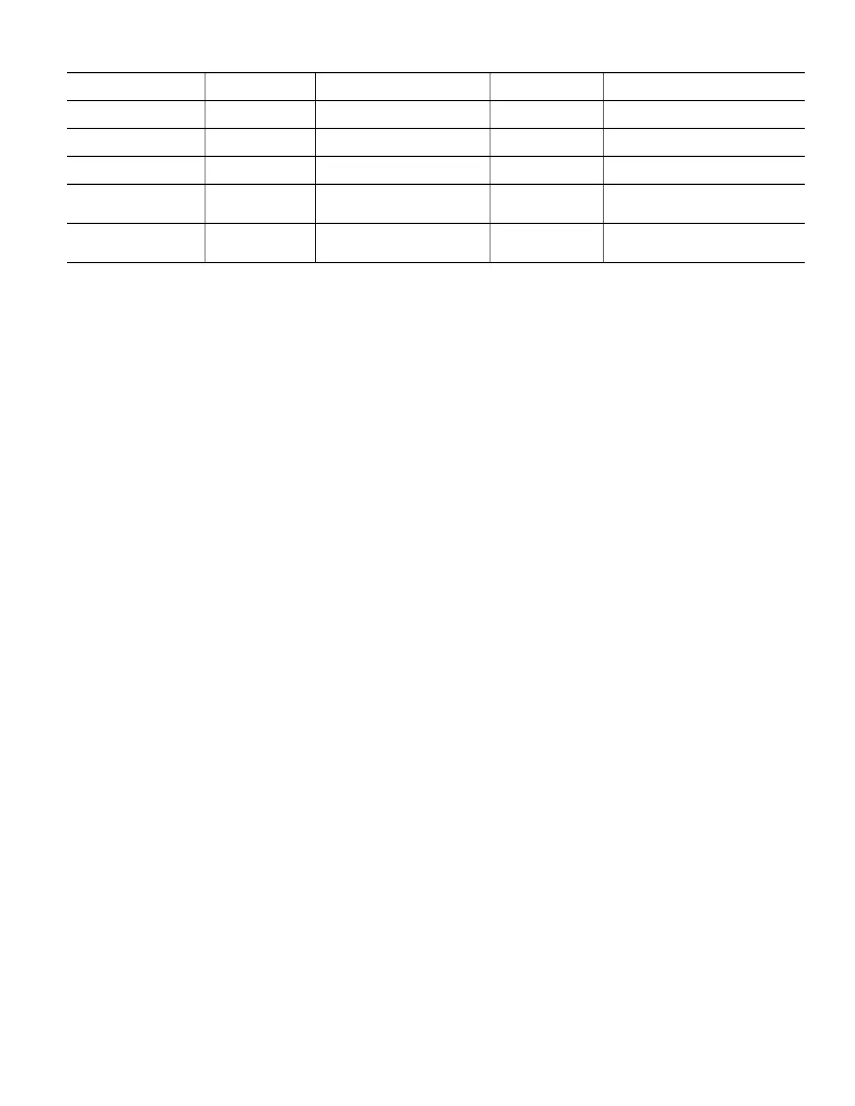
Table 4 — RTU Open Alarms (cont)
POINT NAME
BACnet Object
NAME
ACTION TAKEN BY
CONTROL
RESET METHOD PROBABLE CAUSE

 Loading...