13
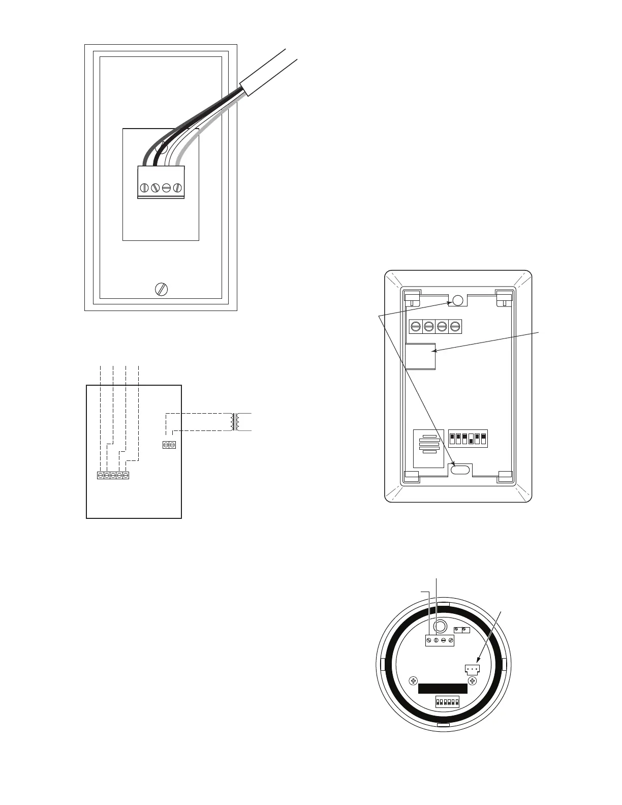
Fig. 11 — Typical Rnet Communication Sensor
Wiring
Fig. 12 — Indoor/Outdoor Air Quality (CO
2
) Sensor
(33ZCSPTCO2-01 or 33ZCSPTCO2LCD-01) Typical
Wiring Diagram
RELATIVE HUMIDITY SENSORS (SPACE OR DUCT
MOUNTED)
The accessory space humidity sensor or duct humidity sensor
is used to measure the relative humidity of the air within the
space or return air duct. The RH reading is used to control the
Humidi-MiZer
®
option of the rooftop unit. For wiring distanc-
es up to 500 ft (152m), use a 3-conductor, 18 or 20 AWG
shielded cable. The shield must be removed from the sensor
end of the cable and grounded at the unit end. The current loop
power for the sensor is provided by the RTU Open controller as
24vdc. Refer to the instructions supplied with the RH sensor
for electrical requirements and terminal locations. RTU Open
controller configurations must be changed after adding a RH
sensor. See below and Fig. 13 and 14 for typical non-communi-
cating RH sensor wiring.
• J4-1 or J4-4 = 24vdc loop power
• J4-2 or J4-5 = 4-20mA signal input
NOTE: The factory default for dehumidification control is a nor-
mally open humidistat.
Installing Discrete Inputs
COMPRESSOR SAFETY
The compressor safety input provides the RTU Open controller
with feedback to when the compressor is not running and
should be. This feedback can be provided by a Compressor
Lock-Out (CLO) device or current switch when field installed.
Compressor safety is a dedicated input on the configurable in-
put 3 and tells the RTU Open controller when the compressor
is locked out. The normal condition for compressor safety is
good operation. A normally open compressor safety is the fac-
tory default for all units. Follow specific accessory instructions
if installing a CLO device. The CLO should wire into the unit's
Integrated Staging Control (ISC) board (48/50LC 07-26), Cen-
tral Terminal Board (CTB) (all 48/50TC(Q), 48/50HC(Q),
48/50KC(Q) 04-06 units, and 04-06 48/50LC units) or Unit
Control Board (UCB) (48/50FC(Q) 04-07, 48/50GC(Q)
04-06).
NOTE: Input 3 can also be wired into J-5.
Fig. 13 — Space Relative Humidity Sensor Typical
Wiring
Fig. 14 — Duct Relative Humidity Sensor Typical
Wiring
To controller
24 Vac Line
Dedicated Transformer
+
-
24 Vac
or Vdc
8 7 6 5 4
2 1
SENSOR LEGEND
1 +24 Vac/Vdc
2 Gnd (-24 Vac/Vdc)
4 -Thermistor
5 +Thermistor
6 4-20 mA
7 SIG COM
8 0-5 Vdc
Io Vin Gnd Vo
SW2
123456
ON
MOUNTING
HOLES
WIRING
OPENING
Vin – J4-1 or J4-4 24Vdc
Io
– J4-2 or J4-5 -20mA output
SPAN
ZERO
4-20
mA
VAC
or
VDC
GND 0-5V
or
0-10V
123456
ON
RELATIVE HUMIDITY SENSOR
(POLARIZED MALE
CONNECTOR)
J4-1 OR J4-4 + 24 VDC SUPPLY VOLTAGE
J4-2 OR J4-5 (-) 4 TO 20 mA
CURRENT LOOP OUTPUT
TO RTU OPEN

 Loading...