17
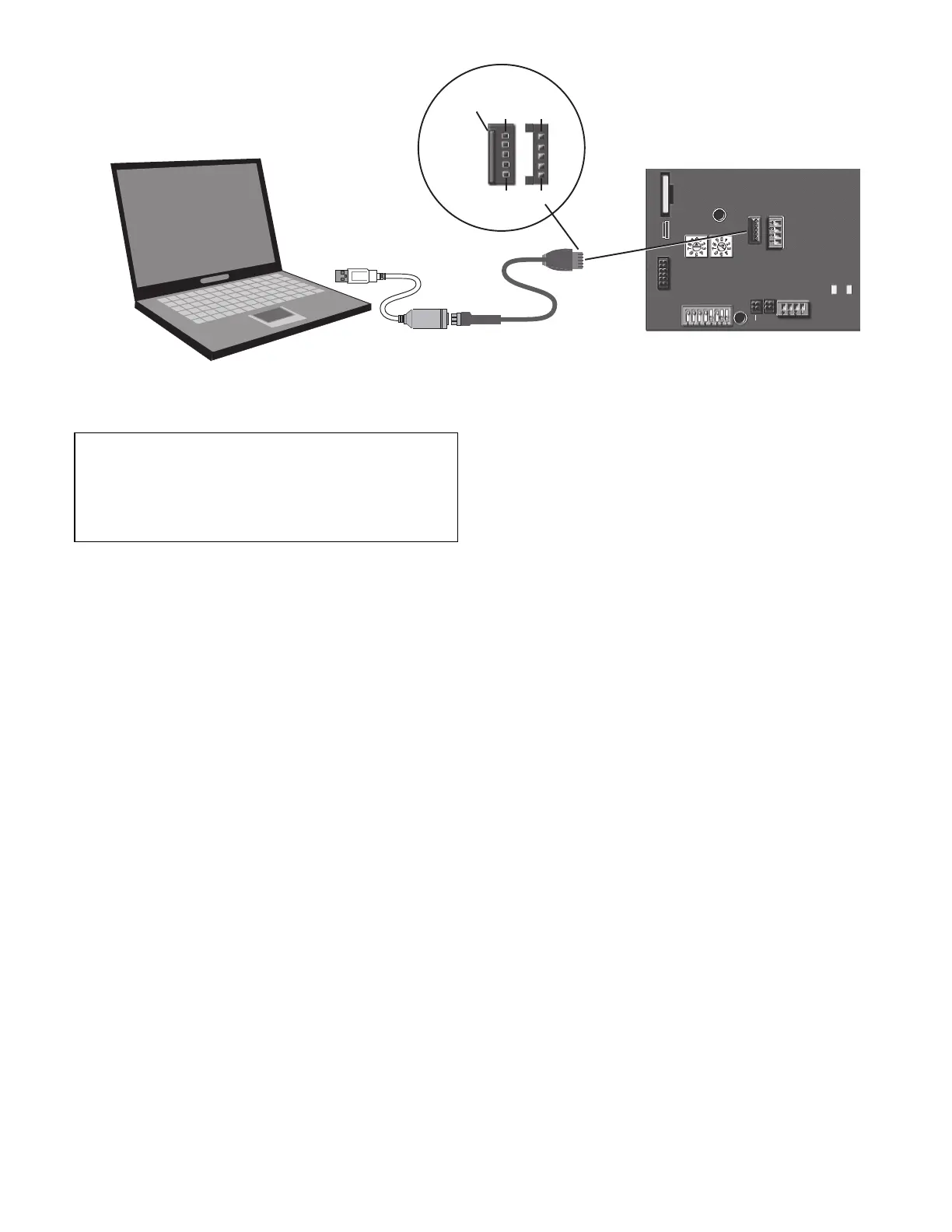
Fig. 20 — PC Running Field Assistant
START-UP
Besides the base unit start-up, there are a few steps to take to
properly start-up the controls. The RTU Open Service Test
function should be used to assist in the base unit start-up and
also allows verification of output operation. Controller config-
uration is also part of start-up. This is especially important
when field accessories have been added to the unit. The factory
pre-configures options installed at the factory. There may also
be additional installation steps or inspection required during
the start-up process.
EcoBlue™ Fan Set Up
The RTU Open controller controls the vane axial fan directly,
therefore the UCB fan set up is not needed. The maximum,
minimum, and heat speed setting can be adjusted to restrict too
much or prevent to too less of air flow. However the control
will speed up the fan as needed during heating or cooling so the
maximum should be the only one needed for duct restrictions.
Additional Installation/Inspection
Inspect the field installed accessories for proper installation,
making note of which ones do or do not require configuration
changes. Inspect the RTU Open Alarms for initial insight to
any potential issues. See troubleshooting section for alarms. In-
spect the SAT sensor for relocation as intended during installa-
tion. Inspect special wiring as directed below.
POWER EXHAUST RELAY POWER
The relay used by the RTU Open board to control power ex-
haust is a dry contact which means it does not have 24vac. This
24vac must be connected to the relay to allow it operate the
power exhaust relay in the PE accessory. A 24vac source
should be provided to the J11-2 pin on the RTU Open control-
ler. This can be provided by the unit's transformer from various
sources.
NOTE: The Factory-installed power exhaust comes pre-con-
figured and does not require routing 24vac as described above.
This factory-installed option is only available on the following
vertical air flow units: 48/50TC(Q) 17-30, 48/50HC 16-30, and
48/50LC 14-26.
SERVICE TEST
The Service Test function can be used to verify proper opera-
tion of compressors, heating stages, indoor fan, power exhaust
fans, economizer, and dehumidification. Use of Service Test is
recommended at initial system start up and during trouble-
shooting. See Appendix A for Service Test Mode table.
Service Test mode has the following changes from normal op-
eration:
• Outdoor air temperature limits for cooling circuits, econo-
mizer, and heating are ignored.
• Normal compressor time guards and other staging delays
are ignored.
• The status of Alarms (except Fire and Safety chain) is ig-
nored, but all alerts and alarms are still broadcast on the
network.
Service Test can be turned ON/OFF from Field Assistant, from
the network, or from the Equipment or System Touch. Once
turned ON, other entries may be made with the display or
through the network. To turn Service Test on, change the value
of Test Mode to ON, to turn Service Test off, change the value
of Test Mode to OFF.
Service Test allows testing of each controller output.
Binary Service Test functions are on when the Default Value is
set to Enable and off when set to Disable.
The output of the Analog Service Test is controlled by percent-
age (0-100%) entered into the Default Value.
It is recommended to return every Service Test variable to Disable
or 0.00 after testing each function (unless that test variable must be
active to test a subsequent function. As in Compressor 2 Test).
All outputs return to normal when Service Test is set to Disable.
FAN TEST
This point allows the board's fan output to be manually turned
On (Enable) and Off (Disable). Other test points that require
the fan for operation will automatically turn the fan on and this
point will still show “Disable.” Fan test can operate simultane-
ously with other Service Test Points. For units equipped with
variable speed fans, the fan test will operate the unit's fan at
minimum VFD output speed.
HIGH SPEED FAN TEST
Use the High Speed Fan Test to activate and deactivate the
Supply Fan (BO-1) output. Note that this output is only appli-
cable if Fan Control is set to Two Speed and Unit Type is NOT
equal to HP O/B Ctrl.
Connect to
computer’s
USB port
Connect to
the Local
Access port
USB Link Kit
RTU Open Controller
Access
Port
J12
P1 P1
P5 P5
LOCAL
ACCESS
PORT
GND
GND
*Therm
mA
*Therm
mA
UI-10
UI-11
SW3
on
COMM
OPTION
CR2032
+
-
SW1 SW2
MSB LSB
TXRX
+12 DVC
Rnet-
Rnet+
GND
RNET
J12
J13
J15
J20
IMPORTANT: Follow the base unit's start-up sequence doc-
umented in its specific instructions. Use the base unit's start-
up check list when performing the start-up. At the end of
this manual there is an additional RTU Open controller
Start-Up Sheet to be completed and included with the base
unit check list.

 Loading...