14
HUMIDISTAT
The accessory humidistat provides the RTU Open controller in-
sight to the relative humidity in the space. The humidistat reads
the RH level in the space and compares it to its setpoint to oper-
ate a dry contact. The humidistat is a dedicated input on the con-
figurable input 9 and tells the RTU Open controller when the RH
level is HIGH or LOW. The normal condition for humidity is
LOW. A normally open humidistat is the factory default control
for the Humidi-MiZer
®
option. To wire in the field:
• J5-8 = 24 VAC source for dry contact
• J5-7 = Signal input
NOTE: Not permitted for use on 48LC 07-26 units due to same in-
put as IGC input.
SINGLE ENTHALPY (OUTDOOR ENTHALPY)
The outdoor enthalpy switch/receiver (33CSENTHSW) senses
temperature and humidity of the air surrounding the device and
calculates the enthalpy when used without an enthalpy sensor.
The relay is energized when enthalpy is high (above 28 BTU/lb
OR dry bulb temperature is above 75°F) and de-energized
when enthalpy is low (below 27 BTU/lb AND dry bulb tem-
perature is below 74.5°F). The enthalpy input is dedicated to
input 8 and tells the RTU Open controller when the outside air
enthalpy is HIGH or LOW. The normal condition for the en-
thalpy input is HIGH. Enthalpy is configured on input 8 in the
factory when it is added as an option.
NOTE: The enthalpy calculation is done using an average altitude
of 1000 ft above sea level.
For field installation, refer to the enthalpy accessory instruc-
tions. For wiring see below (Fig. 15) and Fig. 14. The RTU
Open board provides 24vac on one of the two loose gray wires
in the return air section of the rooftop near the 12-pin econo-
mizer plug. To determine the correct gray, measure the voltage
on the wires with power applied to the unit. If 24-vac is sensed,
then that is the gray wire that is connected to the RTU Open
board at J2-7. The other is the signal for input 8, connect it to
the LOW Enthalpy terminal on the enthalpy switch/receiver.
Tie into the 12-pin economizer plug on pin 4 or the black wire
connected to the actuator for the enthalpy's GND connection.
Power can also be provided direct from the unit transformer
and J5 terminal on the RTU Open controller.
• J2-7 or J5-2 = 24 VAC for enthalpy switch power
• J2-6 or J5-1 = input signal
DIFFERENTIAL ENTHALPY
Differential enthalpy control requires both an enthalpy
switch/receiver (33CSENTHSW) and an enthalpy sensor
(33CSENTSEN). The enthalpy sensor must be installed in the
field as the factory can only provide single enthalpy. The en-
thalpy sensor must be mounted in the return airstream and cal-
culates the enthalpy of the indoor air. The relay is energized
when the enthalpy detected by the return air enthalpy sensor is
less than the enthalpy at the enthalpy switch/receiver. The relay
is de-energized when the enthalpy detected by the return air en-
thalpy sensor is greater than the enthalpy at the enthalpy
switch/receiver (differential enthalpy control).
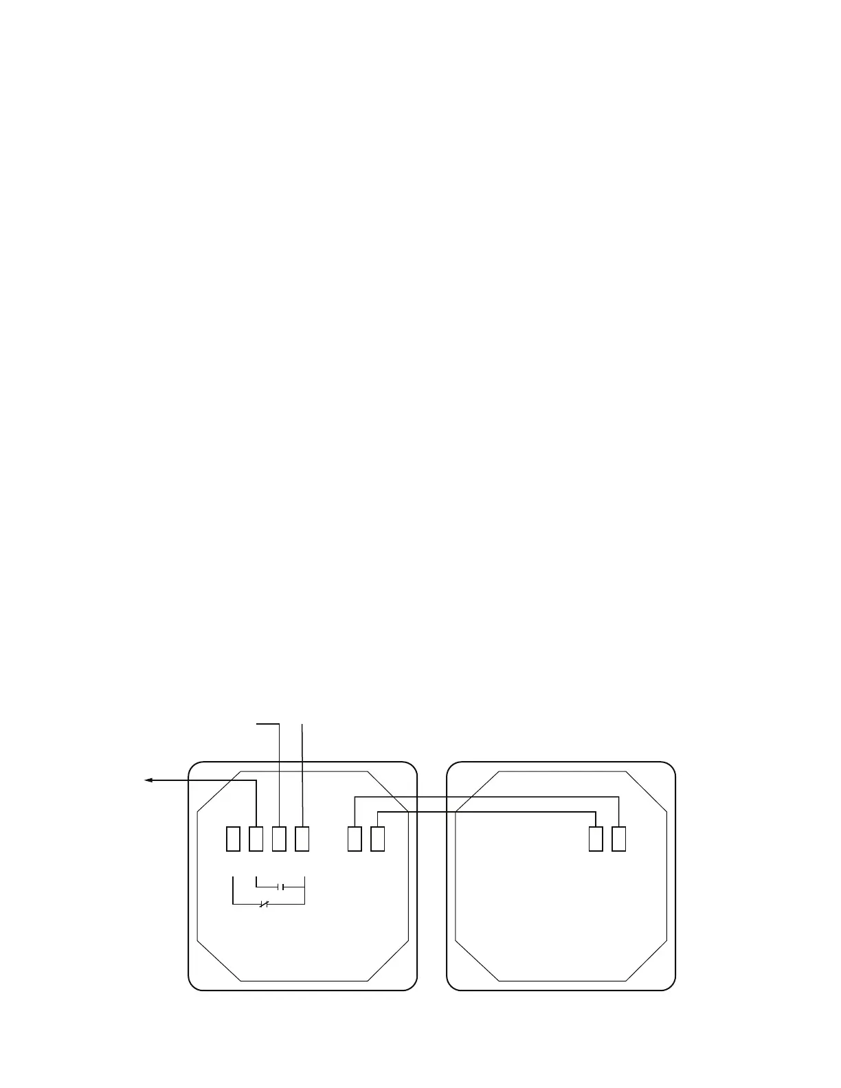
To wire return air enthalpy sensor:
Connect the 4-20 mA In terminal on the enthalpy switch/ re-
ceiver to the 4-20 mA Out terminal on the return air enthalpy
sensor. Connect the 24-36 VDC Out terminal on the enthalpy
switch/receiver to the 24-36 VDC In terminal on the return air
enthalpy sensor. (See Fig. 15.)
FIRE SHUTDOWN
The fire shutdown input is provided for unit shutdown in re-
sponse to a fire alarm or smoke detector. The fire shutdown in-
put is dedicated to input 5 and tells the RTU Open controller
when to shutdown due to smoke detection or fire alarm system.
The normal condition for fire shutdown is there is no fire
alarm. The unit may have factory installed smoke detector(s);
refer to the base unit installation instructions for details on any
adjustments required during unit installation. Fire shutdown is
always factory configured for a normally open smoke detector.
For field installation of a smoke detector see instructions for
that specific accessory. See below and the troubleshooting sec-
tion for wiring at the unit's Integrated Staging Control (ISC)
board (48/50LC 07-26), Central Terminal Board (CTB) (all
48/50TC(Q), 48/50HC(Q), 48/50KC(Q) 04-06 units, and 04-06
48/50LC units) or Unit Control Board (UCB) (48/50FC(Q)
04-07, 48/50GC(Q) 04-06).
•ISC, CTB or UCB - UNIT SHUTDOWN - 24v OUT =
24 VAC source
•ISC, CTB or UCB - UNIT SHUTDOWN - Smoke
Alarm = Signal input to RTU Open controller
NOTE: Input 5 can also be wired into J5-3.
Fig. 15 — Enthalpy Switch and Sensor Wiring
HI
ENTHALPY
GND 24
VAC
4-20
mA
IN
24-36
VDC
OUT
24-36
VDC
IN
4-20
mA
OUT
LO
W
GRY
GND (C)
J2-7 or 24vac (R)
33CSENTHSW
J2-6
GRY
33CSENTSEN
BRN

 Loading...