20
Purge Time – The maximum amount of time used for a pre-
occupancy purge.
Range = 0 to 240 minutes
Default = 60 minutes
Unocc Free Cool Enable – Set to enable or disable the econo-
mizer for night time free cooling (NTFC) operation.
Range = Disable/Enable
Default = Disable
Setpoint Separation – Sets the minimum separation gap in
which setpoints can be set.
Range = 2 to 10°F
Default = 5°F
Occupancy Source – Tells the controller which method of oc-
cupancy control to use in determining occupancy of the roof-
top. Refer to Occupancy in the operation section for detail on
each specific operation function.
Range = Always Occupied, BACnet Schedule, BAS On/Off,
or Remote Occ Input
Default = Always Occupied
INPUTS
Input 1 Function – This input is an analog input and can be
configured to be one of four different inputs: No Sensor, IAQ
Sensor, OAQ Sensor, or Space RH Sensor. Input 1 is wired to
pin J4-4,5,6.
Default = No Sensor
Input 2 Function – This input is an analog input and can be
configured to be one of four different inputs: No Sensor, IAQ
Sensor, OAQ Sensor, or Space RH Sensor. Input 2 is wired to
pin J4-1,2,3
Software Default = No Sensor
Factory Default = IAQ Sensor with factory-installed CO
2
sensor
NOTE: For Inputs 1 and 2, if using Carrier air quality sensors do
not use 24Vdc from RTU Open board. External 24Vdc power sup-
ply required.
Input 3 – This input is a discrete input and can be configured
to be one of six different functions: No Function, Compressor
Safety, Fan Status, Filter Status, Remote Occupancy, or Door
Contact. This input can also be configured to be either a Nor-
mally Open (N/O) or a Normally Closed (N/C) switch. Input 3
is factory wired to pin J1-2. Field accessories can be wired to
its parallel pin J5-5.
Factory Default = Compressor Safety and N/O
Input 5 – This input is a discrete input and can be configured
to be one of six different functions: No Function, Fire Shut-
down, Fan Status, Filter Status, Remote Occupancy, or Door
Contact. This input can also be configured to be either a Nor-
mally Open (N/O) or a Normally Closed (N/C) switch. Input 5
is factory wired to pin J1-10. Field accessories can be wired to
its parallel pin J5-3.
Software Default = Fire Shutdown and N/C
Factory Default = Fire Shutdown and N/O
Input 8 – This input is a discrete input and can be configured
to be one of six different functions: No Function, Enthalpy
Switch, Fan Status, Filter Status, Remote Occupancy, or Door
Contact. This input can also be configured to be either a Nor-
mally Open (N/O) or a Normally Closed (N/C) switch. Input 8
is factory wired to pin J2-6. Field accessories can be wired to
its parallel pin J5-1.
Software Default = Enthalpy Switch and N/O
Factory Default = No Function and N/O without factory-in-
stalled enthalpy sensor
Input 9 – This input is a discrete input and can be configured
to be one of seven different functions: No Function, Humidi-
stat, Fan Status, Filter Status, Remote Occupancy, Door Con-
tact, or IGC Override. This input can also be configured to be
either a Normally Open (N/O) or a Normally Closed (N/C)
switch. Input 9 is factory and field wired to pin J5-7.
Factory Default = Humidistat and N/O
NOTE: For 48LC 07-26 Units (gas heat units) this decision is
automatically set to IGC Override and is factory wired.
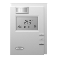
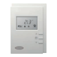
Space Sensor Type – This tells the controller what type of
space sensor is installed to run the unit. The four types that can
be used are: a standard 10k Type II thermistor (T55), sensor
with a setpoint offset slider bar (T56), or a communicating sen-
sor (SPT Sensor) and, ZS Sensor.
Range = T55, T56 (Use for T59), SPT Sensor, or ZS Sensor
Default = T55
ZS Sensor Type – The type of local space temperature sensor.
Range = ZS Base, ZS Plus, ZS Pro
Default = None
T5x Override Duration – Sets the override time duration the
unit will change from unoccupied to occupied when the over-
ride button is pushed on the space sensor.
Range = 0-24 hours
Default = 1 hour
Rnet Port – input for communicating sensor or Equipment
Touch™ Terminal J13 - 1, 2, 3, 4
Range = SPT Sensor, ZS Sensor, or Equipment Touch
Default = None
SERVICE CONFIGURATION
Unit Type – This tells the control what type of unit it is con-
trolling. Heat/Cool refers to gas and electric heat units. LC
WeatherExpert
®
refers to a special 3 stage/2 compressor unit.
HP O/B Ctrl refers to a heat pump unit which requires revers-
ing valve control. HP Y1/W1 Ctrl refers to a heat pump unit
whose reversing valve is built in to the cooling or heating call.
This decision is factory configured for the specific unit type as
supplied.
NOTE: When unit type is set to LC WeatherExpert other configu-
ration settings in the Service Configuration menu will become
hidden from user's view. The configurations that become hidden
include Compressor Stages, Face Split Coil, Fan Control.
Compressor Stages – This refers to the number of mechanical
cooling stages available on a specific unit. For LC size 07-26
units this setting is “Three Stage” and is not a visible menu
configuration.
Factory Default = “Three Stage” for LC size 07-26 units .
Economizer Exists – This indicates if there is an economizer
installed on the unit.
Factory Default = NO if no economizer, or YES if there is
an economizer installed.
Fan Control – This refers to the type of fan control for the given
unit. If Unit Type is selected to LC WeatherExpert, then this is set
to Variable Speed, and is not a visible menu configuration.
Factory Default = Variable Speed for LC size 07-26 units
and FC/GC units
VFD Input – Defines the electrical control signal used by the
VFD's input. Applies to Variable Speed fan control only.
Range = 2-10VDC or 0-10VDC
Factory Default = 2-10 VDC and 0-10VDC on FC/GC units
Show VFD Config As – Sets the VFD control in terms of Per-
centage for typical VFDs or Voltage for ECM motor control.
Factory Default = Percentage
 Loading...
