15
FILTER STATUS
The filter status accessory is a field-installed accessory. This
accessory detects plugged filters. When installing this accesso-
ry, the unit must have a free input (input 3, 5, 8, or 9). One of
the dedicated functions (Humidistat, Fire shutdown, Enthalpy,
or Compressor safety) must not be in use to configure Filter
Status. Refer to the configuration section for details on config-
uring inputs for specific functions and state. Refer to Fig. 1 for
wire terminations at J5.
FAN STATUS
The fan status accessory is a field-installed accessory. This ac-
cessory detects when the indoor fan is moving air. When in-
stalling this accessory, the unit must have a free input (input 3,
5, 8, or 9). One of the dedicated functions (Humidistat, Fire
shutdown, Enthalpy, or Compressor safety) must not be in use
to configure Fan Status. Refer to the configuration section for
details on configuring inputs for specific functions and state.
Refer to Fig. 1 for wire terminations at J5.
REMOTE OCCUPANCY
The remote occupancy accessory is a field-installed accessory.
This accessory provides an input to change the units occupancy
status. When installing this accessory, the unit must have a free
input (input 3, 5, 8, or 9). One of the dedicated functions (Hu-
midistat, Fire shutdown, Enthalpy, or Compressor safety) must
not be in use to configure remote occupancy. Refer to the con-
figuration section for details on configuring inputs for specific
functions and state. Refer to Fig. 1 for wire terminations at J5.
IGC OVERRIDE
The IGC Override input is factory-installed for 48LC 07-26
gas heat units. This input provides an indication that the gas
valve is stuck open and the heat is still operating after any call
for heating has been dropped. This function requires the use of
input 9. Any of the other dedicated functions (Humidistat, Fan
Status, Filter Status, Remote Occupancy, or Door Contact) will
not be in use if IGC Override is configured. Refer to the con-
figuration section for details on configuring inputs for specific
functions and state. Refer to Fig. 5 for wire terminations.
Communication Wiring-Protocols
GENERAL
Protocols are the communication languages spoken by control
devices. The main purpose of a protocol is to communicate in-
formation in the most efficient method possible. Different pro-
tocols exist to provide different kinds of information for differ-
ent applications. In the BAS application, many different proto-
cols are used, depending on manufacturer. Protocols do not
change the function of a controller; just make the front end user
different.
The RTU Open controller can be set to communicate on four
different protocols: BACnet, Modbus, N2, and LonWorks.
Switch 3 (SW3) on the board is used to set protocol and baud
rate. Switches 1 and 2 (SW1 and SW2) are used to set the
board's network address. See Fig. 16 and 17 for protocol switch
settings and address switches. The third party connection to the
RTU Open controller is through plug J19. See Fig. 18 for
wiring. Refer to the RTU Open v3 Integration Guide for more
detailed information on protocols, third party wiring, and
networking.
NOTE: Power must be cycled after changing the SW1-3 switch
settings.
i-Vu BUILDING AUTOMATION SYSTEM
i-Vu
®
is a Carrier front-end and Building Automation System
(BAS). It is a web based network system that uses a native
BACnet over MS/TP communication protocol. The speed of
the network can range from 9600 to 76,800 baud. Open con-
trollers communicate with a proprietary language called Link-
age in i-Vu. Linkage is established automatically and allows
the flow of specific data across Open devices. Refer to i-Vu lit-
erature for more information on i-Vu.
BACnet MS/TP
BACnet Master Slave/Token Passing (MS/TP) is used for com-
municating BACnet over a sub-network of BACnet-only con-
trollers. This is the default Carrier communications protocol.
Each RTU Open module acts as an MS/TP Master. The speed
of an MS/TP network can range from 9600 to 76.8K baud.
Physical Addresses can be set from 01 to 99.
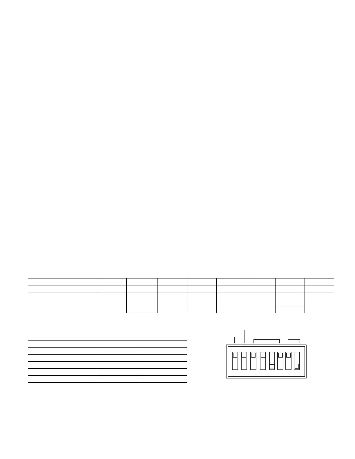
Fig. 16 — RTU Open Controller SW3 Dip Switch Settings
SW3 Protocol Selection
PROTOCOL DS8 DS7 DS6 DS5 DS4 DS3 DS2 DS1
BACnet MS/TP (Master) Unused OFF OFF OFF ON OFF Select Baud Select Baud
Modbus (Slave) Unused OFF OFF ON ON OFF Select Baud Select Baud
N2 (Slave) Unused OFF OFF OFF ON ON OFF OFF
LonWorks Unused ON ON OFF ON OFF OFF ON
NOTE:
DS = Dip Switch
BACnet MS/TP SW3 example shown
Baud Rate Selections
BAUD RATE DS2 DS1
9,600 OFF OFF
19,200 ON OFF
38,400 OFF ON
76,800 ON ON
UNUSED
(OFF)
(ON)
COMM
OPTION
PORT
SET TO MSTP
(MASTER)
SET TO
38.4k
BAUD
PROTOCOL SELECTOR DIP SWITCHES

 Loading...