Do you have a question about the Casio CDP-120 and is the answer not in the manual?
| Sound effects | Reverberation |
|---|---|
| Number of speakers | 2 |
| Chorus effects quantity | 5 |
| Maximum polyphony (notes) | 48 |
| Reverberation effects quantity | 10 |
| USB version | 2.0 |
| USB connector type | USB Type-B |
| Keys quantity | 88 keys |
| Product color | Black |
| Depth | 286 mm |
|---|---|
| Width | 1322 mm |
| Height | 129 mm |
| Weight | 11400 g |
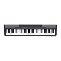
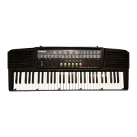
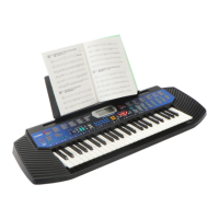
Key technical specifications of the CDP-120 electronic keyboard, including features and dimensions.
Illustrates the main components and their interconnections within the CDP-120 system.
Details of the Main PCB (M914-MDA1) and its primary components.
Details of the Power Amp PCB (M914-PSA1) and its primary components.
Details of the Keyboard PCBs (M914-KYA1, KYB1, KYC1) and their components.
Explanation of the key matrix and contact logic for note detection.
Identifies keys with their note names (e.g., A0, C#1).
Maps buttons to their corresponding function or sound selection.
Visual representation of the Main PCB (M914-MDA1) component placement.
Visual representation of the Power Amp PCB (M914-PSA1) component placement.
Visual layout of the M914-KYA1 keyboard PCB.
Visual layout of the M914-KYB1 keyboard PCB.
Visual layout of the M914-KYC1 keyboard PCB.
Essential safety tips and preparation steps before disassembling the unit.
Steps for removing the main panel unit from the chassis.
Steps for disconnecting FFCs and connectors from the main panel unit.
Steps for removing the right and left side cases.
Steps for removing the right and left inner side cases.
Procedure for removing the main PCB.
Procedure for removing the power amp PCB.
Steps for desoldering and removing the left and right speakers.
Initial steps for removing the keyboard assembly from the chassis.
Final steps for removing the keyboard assembly from the chassis.
Instructions and tool specifications for removing individual keys.
Detailed steps for inserting tools and lifting keys.
Steps for correctly installing keys back into the keyboard chassis.
Procedure for removing hammers using tweezers and a fulcrum point.
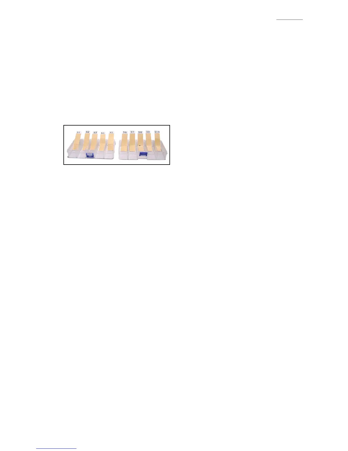
Information on identifying hammer types by code and visual cues.
Guide to correct placement of hammers based on type.
Steps for correctly installing hammers into the keyboard mechanism.
Steps for removing the keyboard PCBs from the unit.
Steps for reconnecting and securing the keyboard PCBs.
Procedures and requirements before starting the diagnostic program.
How to enter and navigate the diagnostic mode.
How to perform and interpret the button check.
How to perform and interpret the ROM version check.
How to perform and interpret the ROM checksum test.
How to perform and interpret the pedal check.
How to perform and interpret the USB connection check.
Diagram showing the internal components of the CDP-120.
Detailed diagram of the keyboard unit components.
List of all replaceable parts with their codes and specifications.
Parts list for the Main and Power Amp PCBs.
Parts list for Keyboard PCBs and keyboard unit components.
Parts list for panel units, side panels, and main case components.
List of accessories like music stand, pedal, AC adaptor, and cords.
Detailed schematic of the Main PCB (M914-MDA1).
Detailed schematic of the Power Amp PCB (M914-PSA1).
Detailed schematic of the M914-KYA1 keyboard PCB.
Detailed schematic of the M914-KYB1 keyboard PCB.
Detailed schematic of the M914-KYC1 keyboard PCB.