EasyManuals Logo
Home>Cisco>Network Router>1100 Series

Cisco 1100 Series Hardware Installation Guide

Cisco 1100 Series
44 pages
To Next Page IconTo Next Page
To Previous Page IconTo Previous Page
Page #7 background imageLoading...
Page #7 background image
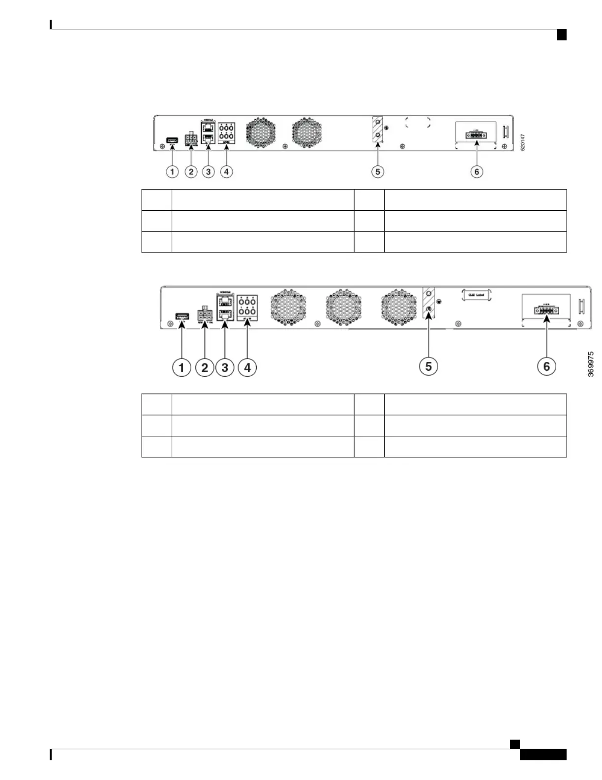
Figure 3: C1100TG-1N32A - Rear View
6-pin Power Connector2USB 3.01
ASYNC LED4RJ-45 Console, AUX3
Power Supply6Grounding Attachment5
Figure 4: C1100TG-1N24P32A and C1100TGX-1N24P32A - Rear View
6-pin Power Connector2USB 3.01
ASYNC LED4RJ-45 Console, AUX3
Power Supply6Grounding Attachment5
LED Indicators
The following figures and table summarizes the LED indicators that are located on the chassis of the Cisco
1100 Terminal Gateway Routers.
Hardware Installation Guide for the Cisco 1100 Terminal Gateway
3
About Cisco 1100 Terminal Gateway Routers
LED Indicators

Table of Contents

Other manuals for Cisco 1100 Series

Questions and Answers:

Question and Answer IconNeed help?

Do you have a question about the Cisco 1100 Series and is the answer not in the manual?

Cisco 1100 Series Specifications

General IconGeneral
BrandCisco
Model1100 Series
CategoryNetwork Router
LanguageEnglish

Related product manuals