12
4 Connect the Router to the Network
This section provides information about cables and ports and attaching the router to the network.
• Console and Auxiliary Port Cable Connections, page 12
• Connect the Fast Ethernet Management Port Cable, page 14
• Connect Native Gigabit Ethernet Cables, page 14
• Connect the Port Adapter Cables, page 18
• Install the Cables in the Cable-Management Bracket, page 19
Warning
The ports labeled “Ethernet,” “10BaseT,” “Token Ring,” “Console,” and “AUX” are safety extra-low voltage (SELV)
circuits. SELV circuits should only be connected to other SELV circuits. Because the BRI circuits are treated like
telephone-network voltage, avoid connecting the SELV circuit to the telephone network voltage (TNV) circuits.
Statement 22
Console and Auxiliary Port Cable Connections
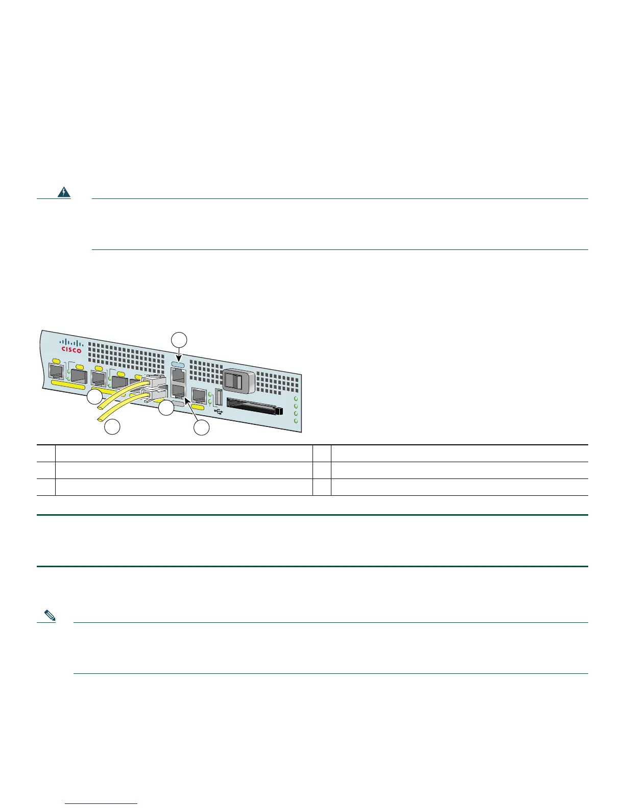
Figure 9 Console and Auxiliary Port RJ-45 Connectors
Step 1 Before connecting a terminal to the console port, configure the terminal to match the router console port as follows:
9600 baud, 8 data bits, no parity, 1 stop bits (9600 8N1).
Step 2 After you establish normal router operation, you can disconnect the terminal.
The Cisco 7201 router uses RJ-45 ports for both the auxiliary port and the console port.
Note You must supply your own interface cable between the auxiliary port and the equipment you are connecting. For
console and auxiliary port pinouts, see Appendix A, “Specifications,” of the online Cisco 7201 Installation and
Configuration Guide at
http://www.cisco.com/en/US/docs/routers/7200/install_and_upgrade/7201_install_config/7201_icg.html.
1
Auxiliary port
4
Cable to console terminal or DTE
2
Console port
5
Cable to modem or DCE
3
RJ-45 connector
170866
G
E 0/0
G
E 0/1
G
E 0/2
GE
0/3
AU
X
CO
NSO
LE
M
N
G
M
NT U
SE O
N
LY
FE
LIN
K
0
FE 0/0
RJ45
SFP
SFP
SFP
SFP
LINK/A
CTV
A
LARM
PW
R O
K
STATUS
CF
AC
TV
COMPACT FLASH
LINK/A
CTV
RX
TX
LIN
K/ACTV
LINK/A
CTV
RX
TX
EN
RJ45
EN
1
2
3
4
5
Cisco
7201
 Loading...