46
Use the following procedure to install an SFP module:
Step 1 Attach an ESD-preventive wrist strap between you and an unpainted chassis surface.
Step 2 Locate the label on the SFP module and turn the SFP module so the label is on top and the alignment groove is on the
bottom.
Note The SFP module is keyed so that it cannot be inserted incorrectly.
Step 3 Insert the SFP module into Gigabit Ethernet port 0/0, 0/1, 0/2, or 0/3. The SFP module snaps into place when you have
completely and properly inserted it.
Step 4 Repeat Step 2 and Step 3 if you are inserting a second, third, or fourth SFP module.
Note Do not remove the plug from the SFP optical bores until you are ready to install the network interface optical fiber
cable. Save the plug for future use.
Step 5 Clean the optical fiber cable before attaching it to the SFP module. For information, see the
Inspection and Cleaning Procedures for Fiber-Optic Connections
document at
http://www.cisco.com/en/US/tech/tk482/tk876/technologies_white_paper09186a0080254eba.shtml and the
Compressed Air Cleaning Issues for Fiber-Optic Connections
document at
http://www.cisco.com/en/US/tech/tk482/tk611/technologies_white_paper09186a00801b08da.shtml.
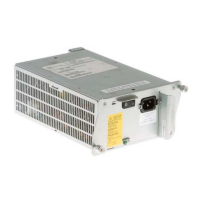
Remove and Replace a Power Supply
This section provides information about removing and replacing an AC or DC power supply. Because of the power supply
redundancy, there is no need to power off the Cisco 7201 router before removing one of the AC or DC power supplies.
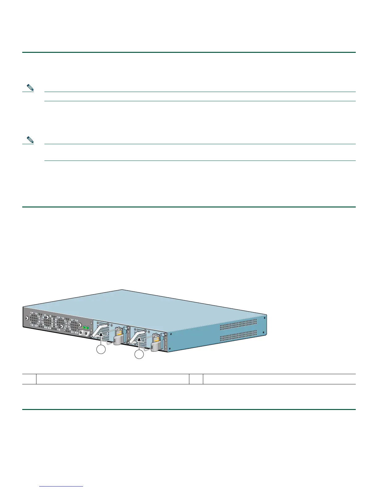
The Cisco 7201 has two of the same type of power supplies in power supply slot 1 and power supply slot 2. (See Figure 35.)
Figure 35 Power Supply Slot 1 and Slot 2
Remove the AC Power Supply
Step 1 Unplug the power cable from the power source.
1
Power supply slot 1
2
Power supply slot 2
230086
PWR
SLOT 2
PWR
SLOT 1
PWR
SLOT 1 OK
T
H
IS
U
N
I
T
M
A
Y
H
A
V
E
M
O
R
E
T
H
A
N
O
N
E
P
O
W
E
R
S
U
P
P
L
Y
C
O
N
N
E
C
T
I
O
N
. A
L
L
C
O
N
N
E
C
T
IO
N
S
M
U
S
T
B
E
R
E
M
O
V
E
D
T
O
D
E
-
E
N
E
R
G
IZ
E
T
H
E
U
N
IT
PWR
SLOT 2 OK
1
2
 Loading...