3-4
Cisco Aironet 1570 Series Outdoor Access Point Hardware Installation Guide
OL-32138-01
Chapter 3 Troubleshooting
Monitoring the Access Point LEDs
Monitoring the Access Point LEDs
If your access point is not working properly, look at the LEDs on the bottom of the unit. You can use
them to quickly assess the status of the unit.
Note It is expected that there will be small variations in LED color intensity and hue from unit to unit. This is
within the normal range of the LED manufacturer specifications and is not a defect.
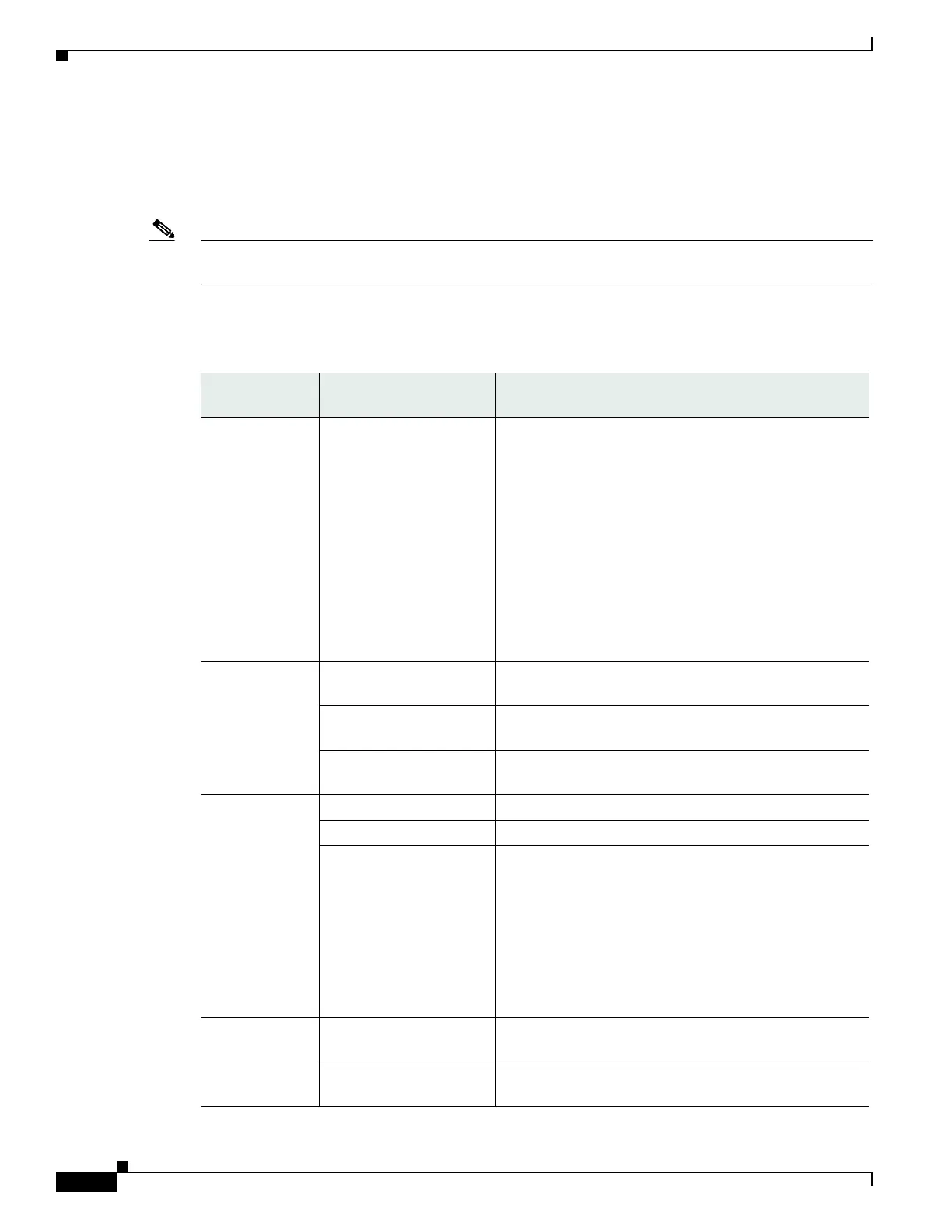
The access point LED signals are listed in Table 3-1.
Table 3-1 Access Point LED Signals
LED Message
Type
Color Meaning
Boot loader
status sequence
Blinking Green Boot loader status sequence:
• DRAM memory test in progress
• DRAM memory test OK
• Board initialization in progress
• Initializing FLASH file system
• FLASH memory test OK
• Initializing Ethernet
• Ethernet OK
• Starting Cisco IOS
• Initialization successful
Boot loader
warnings
Blinking Amber Configuration recovery is in progress (the MODE button
has been pushed for 2-3 seconds)
Solid Red There is an Ethernet failure or an image recovery (the
MODE button has been pushed for 20-30 seconds)
Blinking Green An image recovery is in progress (the MODE button has
been released)
Boot loader
errors
Solid Red There has been a DRAM memory test failure
Blinking Red and Amber There has been a FLASH file system failure
Blinking Red and Off This sequence may indicate any of the following:
• Environment variable failure
• Bad MAC address
• Ethernet failure during image recovery
• Boot environment failure
• No Cisco image file
• Boot failure
Cisco IOS
errors
Solid Red There has been a software failure; a disconnect then
reconnect of the unit power may resolve the issue
Cycling through Red,
Green, Amber and Off
This is a general warning of insufficient inline power.
 Loading...