4-8
Cisco ASR 1000 Series Aggregation Services Routers Hardware Installation Guide
OL-13208-11
Chapter 4 Cisco ASR 1000 Series Router SPA Interface Processors (SIPs)
SPA Interface Processor Slot Numbering
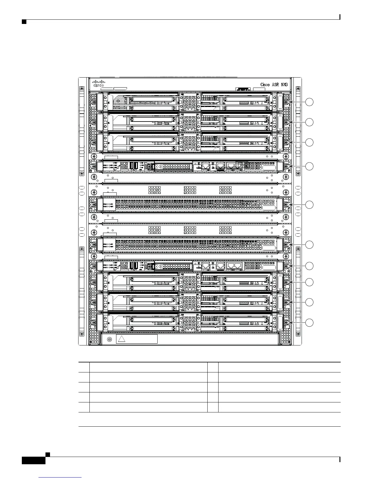
Figure 4-6 shows the slot numbering for the shared port adapters on the Cisco ASR 1013 Router.
Figure 4-6 Cisco ASR 1013 Router Slot Numbering
1 ASR 1000 Series SIP slot 5 6 Slot F0 with ASR 1000 Series ESP-40
2 ASR 1000 Series SIP slot 4 7 Slot R0 with ASR 1000 Series RP2
3 ASR 1000 Series SIP slot 3 8 ASR 1000 Series SIP slot 2
4 Slot R1 with ASR 1000 Series RP2 9 ASR 1000 Series SIP slot 1
5 Slot F1 with ASR 1000 Series ESP-40 10 ASR 1000 Series SIP slot 0
Note: Slots 10, 9, 8, 7, and 6 reside in Zone 0 and slots 5, 4, 3, 2, and 1 reside in Zone
1.
ASR1000-SIP40
ASR1000-SIP40
ASR1000-SIP40
ASR1000-SIP40
ASR1000-SIP40
ASR1000-SIP40
PWR STATUS
PWR STATUS
PWR STATUS
PWR STATUS
PWR STATUS
PWR STATUS
WARNING: THIS ASSEMBLY CONTAINS
ELECTROSTATIC SENSITIVE DEVICES
RFL
ASR1000-RP-FILLER
RFL
ASR1000-RP-FILLER
FBF
ASR1000-FP-BAFFLE
RFL
ASR1000-RP-FILLER
RFL
ASR1000-RP-FILLER
FBF
ASR1000-FP-BAFFLE
ASR1000-RP2
ASR1000-ESP40
ASR1000-ESP40
ASR1000-RP2
1
2
3
4
5
6
7
8
9
10
279160

 Loading...


