7-2
Cisco ASR 1000 Series Aggregation Services Routers Hardware Installation Guide
OL-13208-11
Chapter 7 Cisco ASR 1004 Router Overview and Installation
Cisco ASR 1004 Router Description
Cisco ASR 1004 Router Description
The Cisco ASR 1004 Router system consists of the following system level components:
• Two Cisco ASR 1000 Series SPA Interface Processor (Cisco ASR1000-SIP10 or Cisco
ASR1000-SIP40)
• One Cisco ASR 1000 Series Embedded Services Processor (Cisco ASR 1000-ESP10, Cisco
ASR 1000-ESP20, or Cisco ASR1000-ESP40)
• One Cisco ASR 1000 Series Route Processor (Cisco ASR1000-RP1 or Cisco ASR1000-RP2)
• Dual (redundant) AC and DC power supplies
This section contains the following topics:
• Front View, page 7-2
• Rear View, page 7-3
Front View
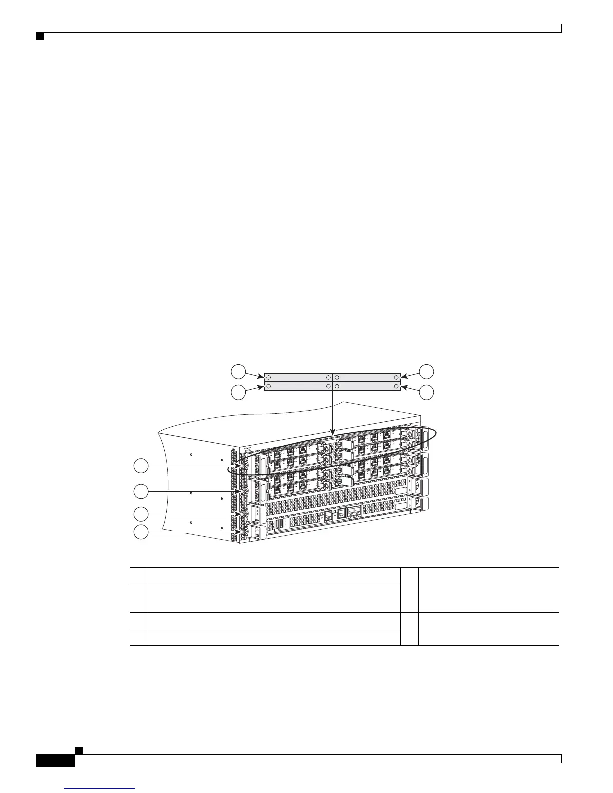
Figure 7-1 shows the Cisco ASR 1004 Router with modules and filler plates installed.
Figure 7-1 Cisco ASR 1004 Router—Front and Side View
1 Slot R0 with ASR 1000 Series Route Processor 5 SPA subslot 2
2 Slot F0 with Cisco ASR1000-ESP10,
Cisco ASR1000-ESP20, or Cisco ASR1000-ESP40
6 SPA subslot 0
3 ASR 1000 Series SIP slot 0 7 SPA subslot 1
4 ASR 1000 Series SIP slot 1 8 SPA subslot 3
280312
MI
N
AC
O
MA
J
S
T
B
Y
A
CTV
S
T
A
T
AS
R1
000-
R
P
1
P
W
R
C
R
I
T
S
P
A
-4XOC3
-
P
O
S
S
T
A
T
U
S
0
1
2
3
C/
A
A
/
L
C
/
A
A
/
L
C
/
A
A
/
L
C
/
A
A/
L
S
P
A
-4XOC3
-
P
O
S
S
T
A
T
U
S
0
1
2
3
C
/
A
A
/
L
C/
A
A
/
L
C
/
A
A/
L
C
/
A
A/
L
S
P
A
-4X
OC3
-
P
O
S
S
T
A
T
U
S
0
1
2
3
C
/
A
A
/
L
C
/
A
A
/
L
C
/
A
A/
L
C
/
A
A
/
L
S
P
A
-
4
X
O
C3
-
P
O
S
S
T
A
T
U
S
0
1
2
3
C
/
A
A
/
L
C
/
A
A/
L
C
/
A
A
/
L
C
/
A
A
/
L
S
P
A
-
4X
O
C
3-
P
OS
S
T
A
T
U
S
0
1
2
3
C
/
A
A
/
L
C
/
A
A
/
L
C
/
A
A
/
L
C
/
A
A
/
L
S
P
A
-
4X
O
C
3-
P
OS
S
T
A
T
U
S
0
1
2
3
C
/
A
A/
L
C
/
A
A/
L
C
/
A
A/
L
C
/
A
A
/
L
S
P
A
-
4X
OC
3-
P
OS
S
T
A
T
U
S
0
1
2
3
C
/
A
A
/
L
C
/
A
A
/
L
C
/
A
A
/
L
C
/
A
A
/
L
S
P
A
-4X
O
C
3-
P
OS
S
T
A
T
U
S
0
1
2
3
C
/
A
A/
L
C
/
A
A
/
L
C
/
A
A/
L
C
/
A
A/
L
BIT
S
C
O
N
A
UX
C
AR
RIE
R
L
I
N
K
M
G
M
T
E
T
HE
R
N
E
T
D
I
S
K
H
D
USB
DF
0
1
1
2
3
4
5
6
8
7

 Loading...


