119
Cisco ASR 9000 Series Aggregation Services Router Getting Started Guide
OL-28417-02
Introduction to the Cisco ASR 9000 Series Aggregation Services Router
Initial Router Configuration
The Cisco ASR 9000 Series enable operators to deploy any combination of Layer 2 and Layer 3 service
applications at an industry-leading price-to-performance ratio. The Cisco ASR 9000 SIP-700 is designed
to complement this ability by, over time, extending the same scalability and reliability to the realm of
traditional transport media such as time-division multiplexing (TDM), Frame Relay, ATM, and Packet
over Sonet (POS), thereby reducing capital expenditures (CapEx) and operating expenses (OpEx), as
well as reducing the time required to develop and deploy new services. It also allows service providers
to continue their deployed services, keeping those revenue streams open, while simultaneously
migrating to the next-generation routing platform that opens up new channels of revenue.
By seamlessly integrating within the same chassis, the SIP-700 and Ethernet line cards provide true
network and device convergence - a key design goal for the Cisco ASR 9000 Series of routers. The Cisco
ASR 9000 SIP-700 only utilizes one line card slot within the Cisco ASR 9000 Series chassis, saving
valuable line-card real estate. Fully integrated with the Cisco ASR 9000 Series synchronization circuitry,
the Cisco ASR 9000 SIP-700 line cards provide standards-based line-interface functions for delivering
and deriving transport-class network timing, enabling support of network-synchronized services and
applications such as mobile backhaul and time-division multiplexing (TDM) migration.
For more information about the Cisco ASR 9000 Series SPA Interface Processor-700, see the Cisco ASR
9000 Series Aggregation Services Router SIP and SPA Hardware Installation Guide.
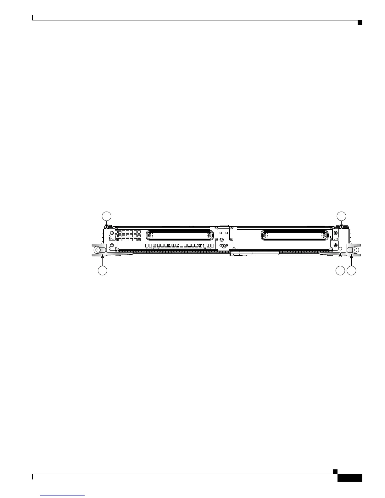
Figure 3 Cisco ASR 9000 Series SPA Interface Processor-700
Initial Router Configuration
The initial configuration of the Cisco ASR 9000 Series Router is determined automatically by the
software when you boot the router; you do not need to set up any general configuration information.
Also, there is no explicit configuration needed to make a particular RSP active. It becomes the active
RSP when chosen automatically by the software upon boot.
Because there is only one RSP pair in this router, the primary RSP choices are RSP0 and RSP1.
Typically, the slot with the lower number is the chosen primary RSP. If that RSP is not available, the
software chooses the RSP in the other slot as the elected Route Process Controller, making it the primary
RSP; the other RSP becomes standby RSP. During switchover, the active role migrates to the standby
RSP.
STAT US
1
0
12000-SIP-600
116871
3
1 2
3
4

 Loading...


