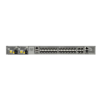
Figure 27: DC Power Supply Guard
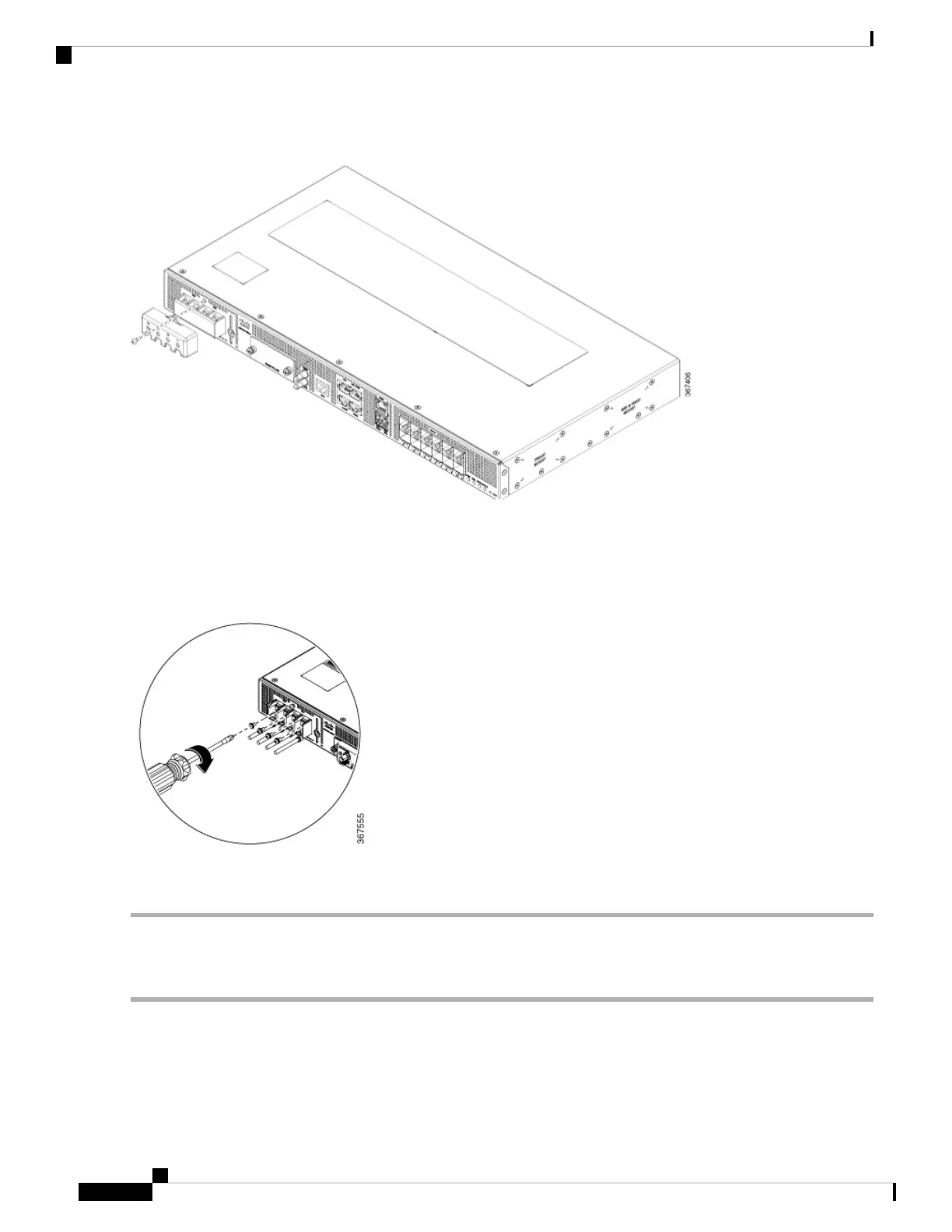
Step 2 Lift the flap and attach the DC supply wires to the designated screws.
Ensure that you follow the polarity marking on the chassis.
Note
Figure 28: Attach the Wires to the DC Power Supply
Step 3 Re-insert the DC power supply guard.
Activate DC Power Supply
Step 1 Remove the tape from the circuit-breaker device handle, and restore power by moving the circuit-breaker device handle
to the On (|) position.
Step 2 Verify the power supply operation by ascertaining that the power supply LEDs (PS0 or PS1) on the front panel are green.
Step 3 If the LEDs indicate a power problem, see the LED Indicators section in the Overview chapter.
Cisco ASR-920-12SZ-A and Cisco ASR-920-12SZ-D Aggregation Services Router Hardware Installation Guide
46
Install the Router
Activate DC Power Supply
 Loading...