Protection Switching Functionality in a Single Link Failure and Recovery
The following figure illustrates protection switching functionality in a single-link failure.
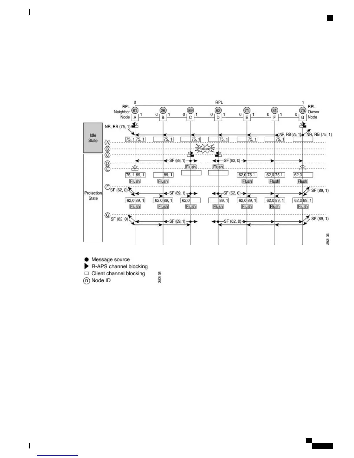
Figure 9: G.8032 Ethernet Ring Protection Switching in a Single-Link Failure
The figure represents an Ethernet ring topology consisting of seven Ethernet ring nodes. The ring protection
link (RPL) is the ring link between Ethernet ring nodes A and G. In this topology, both ends of the RPL are
blocked. Ethernet ring node G is the RPL owner node, and Ethernet ring node A is the RPL neighbor node.
The following sequence describes the steps followed in the single-link failure:
1
A link operates in the normal condition.
2
A failure occurs.
3
Ethernet ring nodes C and D detect a local signal failure (SF) condition and after the hold-off time interval,
block the failed ring port and perform the FDB flush.
4
Ethernet ring nodes C and D start sending Ring Automatic Protection Switching (R-APS) SF messages
periodically along with the (node ID and bidirectional path-protected ring (BPR) identifier pair) on both
ring ports while the SF condition persists.
LAN Switching Configuration Guide Cisco IOS XE Everest 16.5.1 (Cisco ASR 900 Series)
51
ITU-T G.8032 Ethernet Ring Protection Switching
Protection Switching Functionality in a Single Link Failure and Recovery
 Loading...