1-7
Cisco UCS C240 M4 Server Installation and Service Guide
OL-32474-01
Chapter 1 Overview
Replaceable Component Locations
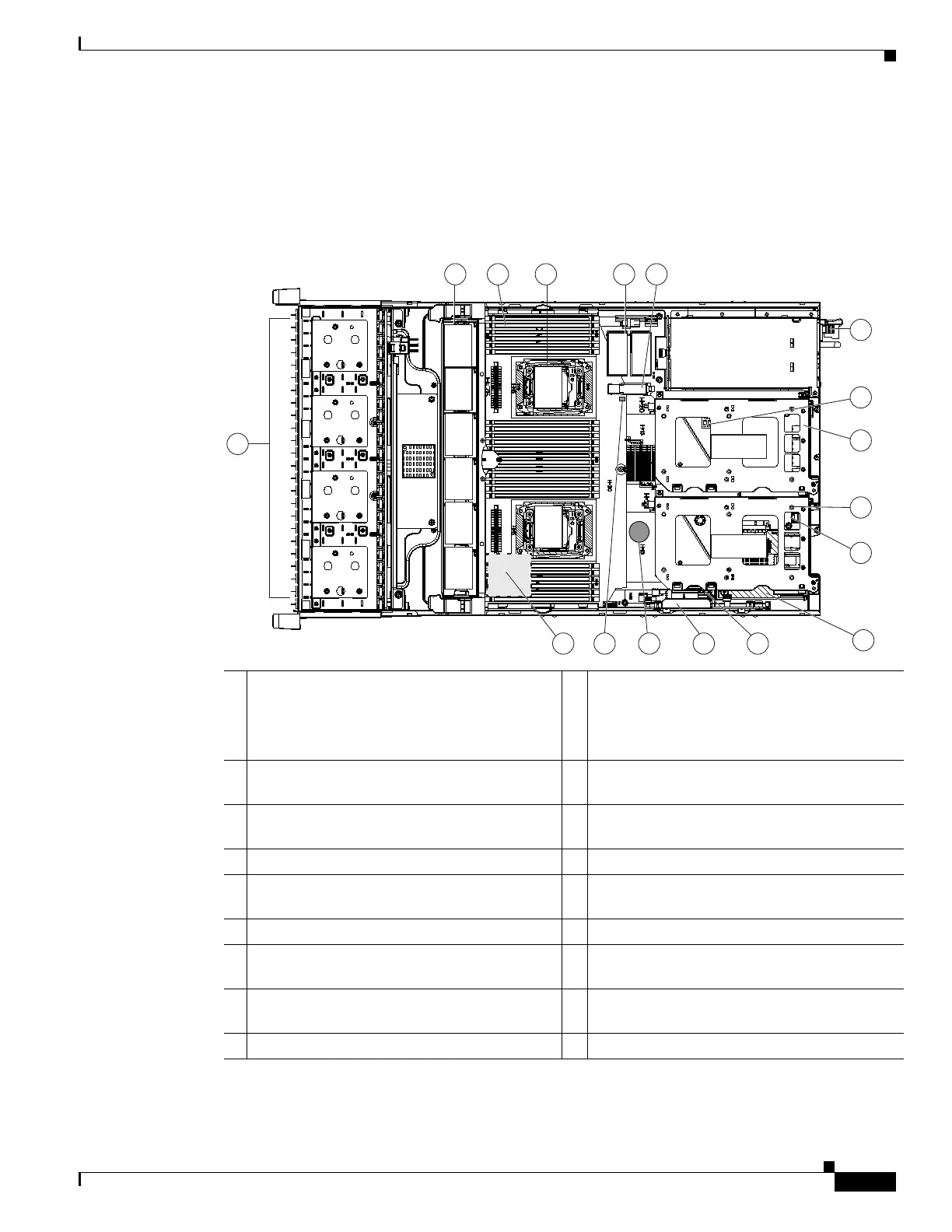
Figure 1-6 shows the locations of the field-replaceable components. The view shown is from the top
down with the top covers and air baffle removed.
Figure 1-6 Replaceable Component Locations
1 Drives (SAS/SATA drives are hot-swappable
and accessed through the front panel)
10 PCIe riser 1 (PCIe slots 1, 2, 3*)
*Slot 3 not present in all versions. See
Replacing a PCIe Card, page 3-43 for riser
options and slot specifications.
2 Fan modules (six, hot-swappable) 11 SATA boot drives (two sockets available only
on PCIe riser 1 option 1C)
3 DIMM sockets on motherboard (up to 24
DIMMs)
12 mLOM card socket on motherboard under
PCIe riser 1
4 CPUs and heatsinks (two) 13 Socket for embedded RAID interposer board
5 Cisco SD card slots on motherboard (two) 14 Cisco modular RAID controller PCIe slot
(dedicated slot and bracket)
6 USB 3.0 slot on motherboard 15 RTC battery on motherboard
7 Power supplies (hot-swappable, accessed
through rear panel)
16 Embedded RAID header for RAID 5 key
8 Trusted platform module (TPM) socket on
motherboard, under PCIe riser 2
17 Supercap power module (RAID backup)
mounting location on air baffle (not shown)
9 PCIe riser 2 (PCIe slots 4, 5, 6)
352948
FAN 06
1
2
3
4
13
5
7
8
9
10
12
1415
16
17
FAN 05
FAN 04
FAN 03
FAN 02
FAN 01
CPU 1
CPU 2
SD1
SD2
Riser 2
Riser 1
11
6
 Loading...