3-2
Cisco UCS C240 M4 Server Installation and Service Guide
OL-32474-01
Chapter 3 Maintaining the Server
Status LEDs and Buttons
Status LEDs and Buttons
This section describes the location and meaning of LEDs and buttons and includes the following topics
• Front Panel LEDs, page 3-2
• Rear Panel LEDs and Buttons, page 3-5
• Internal Diagnostic LEDs, page 3-8
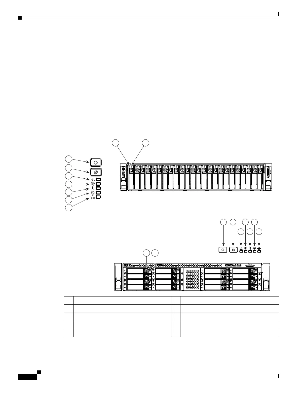
Front Panel LEDs
Figure 3-1 shows the front panel LEDs. Table 3-1 defines the LED states.
The small form factor (SFF) drives, 24-drive version and the SFF drives, 16-drive version are shown.
Figure 3-1 Front Panel LEDs
1 Hard drive fault LED (on each drive tray) 6 Fan status LED
2 Hard drive activity LED (on each drive tray) 7 Temperature status LED
3 Power button/power status LED 8 Power supply status LED
4 Unit Identification button/LED 9 Network link activity LED
5 System status LED
HDD01
HDD03
HDD05
HDD07
HDD02
HDD04
HDD06
HDD08
HDD09
HDD11
HDD13
HDD15
HDD10
HDD12
HDD14
HDD16
975
3 4 6 8
352950
6
7
8
9
5
4
3
HDD01
HDD02
HDD03
HDD04
HDD05
HDD06
HDD07
HDD08
HDD09
HDD10
HDD11
HDD12
HDD13
HDD14
HDD15
HDD16
HDD17
HDD18
HDD19
HDD20
HDD21
HDD22
HDD23
HDD24
1 2
21
 Loading...