3-36
Cisco UCS C240 M4 Server Installation and Service Guide
OL-32474-01
Chapter 3 Maintaining the Server
Installing or Replacing Server Components
Replacing a Software RAID 5 Key Module
The server has a two-pin header on the motherboard for a RAID 5 key module. This module upgrades
the embedded SATA RAID controller options (see Embedded SATA RAID Controller, page C-11).
Step 1 Power off the server as described in Shutting Down and Powering Off the Server, page 3-9.
Step 2 Slide the server out the front of the rack far enough so that you can remove the top cover. You might have
to detach cables from the rear panel to provide clearance.
Caution If you cannot safely view and access the component, remove the server from the rack.
Step 3 Remove the top cover as described in Removing and Replacing the Server Top Cover, page 3-10.
Step 4 Remove any existing software RAID key module:
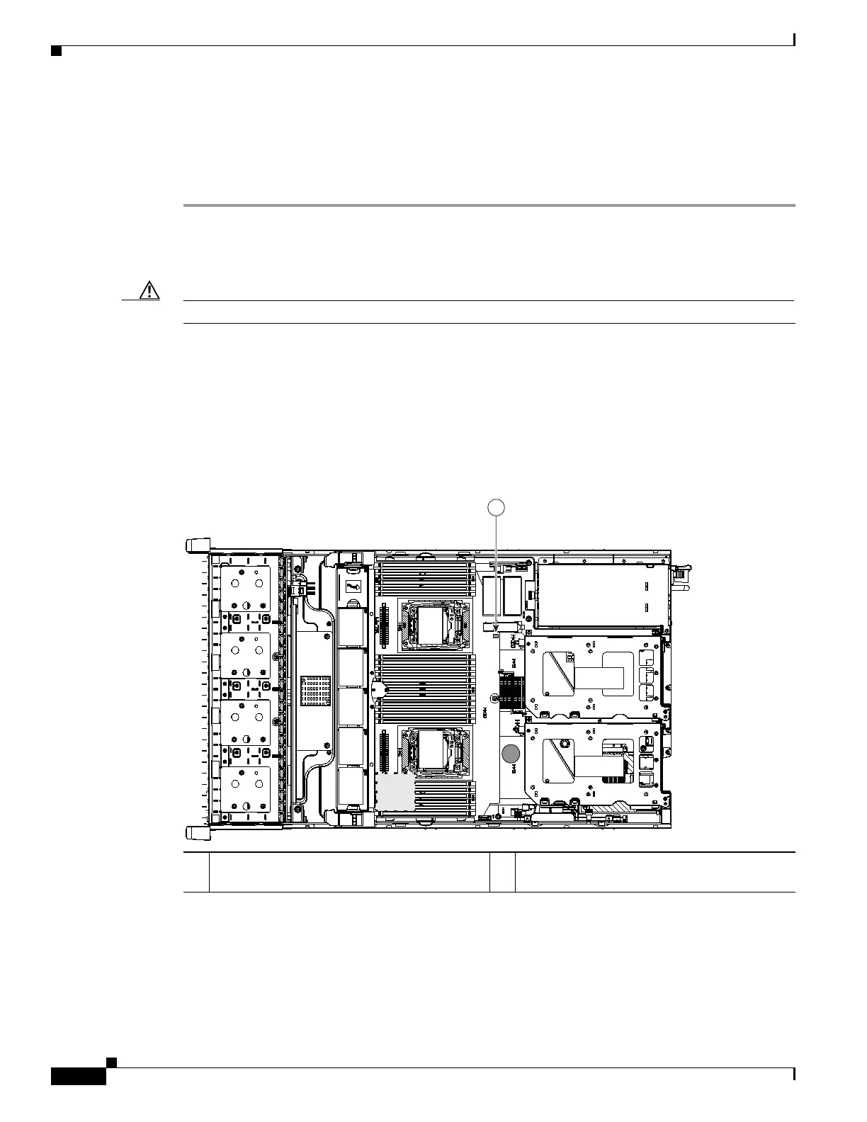
a. Locate the module on the motherboard (see Figure 3-20).
b. Hold the retention clips on the header open while you grasp the RAID key board and pull straight
up (see Figure 3-21).
Figure 3-20 RAID 5 Key Header Location on Motherboard
1 Software RAID 5 key header (adds RAID 5
support)
352963
FAN 05
FAN 04
FAN 03
FAN 0 2
FAN 01
CPU 1
CPU 2
SD1
SD2
Riser 2
Riser 1
1
 Loading...