USB Console Active LED
Left LED On indicates
USB console is active
11Alarm LED - Minor3
Console USB12Alarm LED - Major4
Console RJ-4513Alarm LED - Critical5
Console RJ-45 Active
LED
Right LED On indicates
RJ45 console is active
14Speed LED6
RJ-457
Front and Rear View of Cisco C8500-12X
USB 19Power LED1
USB 010Status LED2
Management Interface11Alarm LED’s3, 4 and 5
Console USB12Management Interface
LEDs
6 and 7
Console RJ-4513Bay 0 - 12x 1/10GE SFP+
ports
8
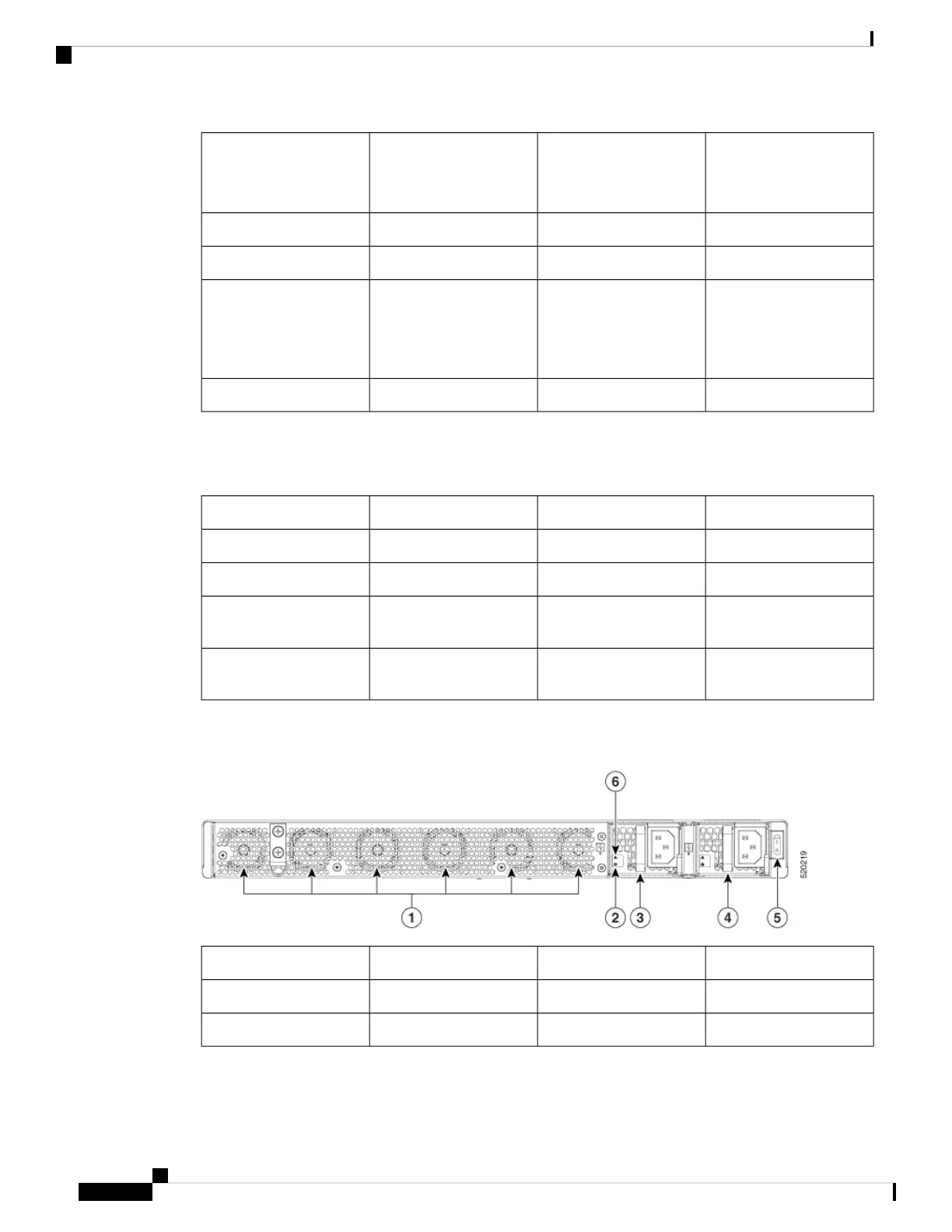
The following figure shows the rear view of of Cisco C8500-12X
Figure 2: Cisco C8500-12X Rear View
Power Switch5Fans1
Power supply failure LED6Power supply input LED2
PEM 0, PEM 13 and 4
Cisco Catalyst 8500 Series Edge Platforms Hardware Installation Guide
4
Overview
Front and Rear View of Cisco C8500-12X
 Loading...


