Amber (FAIL) LED StatusGreen (OK) LED StatusPower Supply Condition
1Hz BlinkingOFFPower Supply Warning events where the power
supply continues to operate (high temperature, high
power and slow fan)
OFF1Hz BlinkingAC Present/3.3VSB on (PSU OFF)
OFFONPower Supply ON and OK
Power Supply Fans
The fans in the power supply module are used for cooling the power supply module itself while system-level
cooling is provided by fans within the chassis. The power supplies do not depend on the system-level fans
for cooling. Fan failure is determined by fan-rotation sensors.
The fans in the power supply modules will run as soon as the power supply is plugged in, even if the power
switch is in the Standby position.
Note
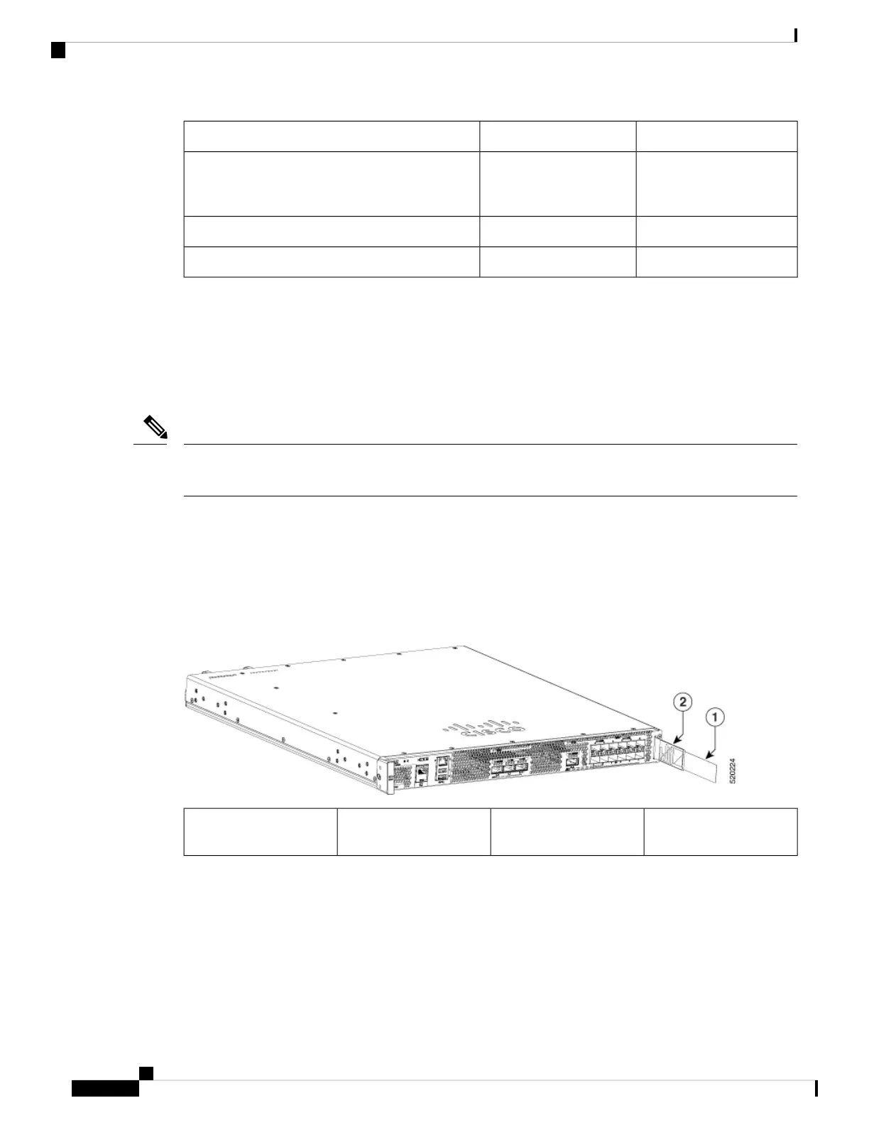
Serial Number and PID/VID Label Location
The following figure show the location of the serial number and the PID/VID label on the Cisco Catalyst 8500
Series Edge Platforms.
Figure 5: Cisco Catalyst 8500 Series Edge Platforms Serial Number and PID/VID Label Location
PID/VID Label2Label Carrier, extended
from chassis
1
Cisco Catalyst 8500 Series Edge Platforms Hardware Installation Guide
8
Overview
Power Supply Fans
 Loading...


