RJ45 and Micro USB
Console
2RFID Tag1
Label Tray4Bay 0 – 12XSFP+:
Configurable as:
12X10/1G
3
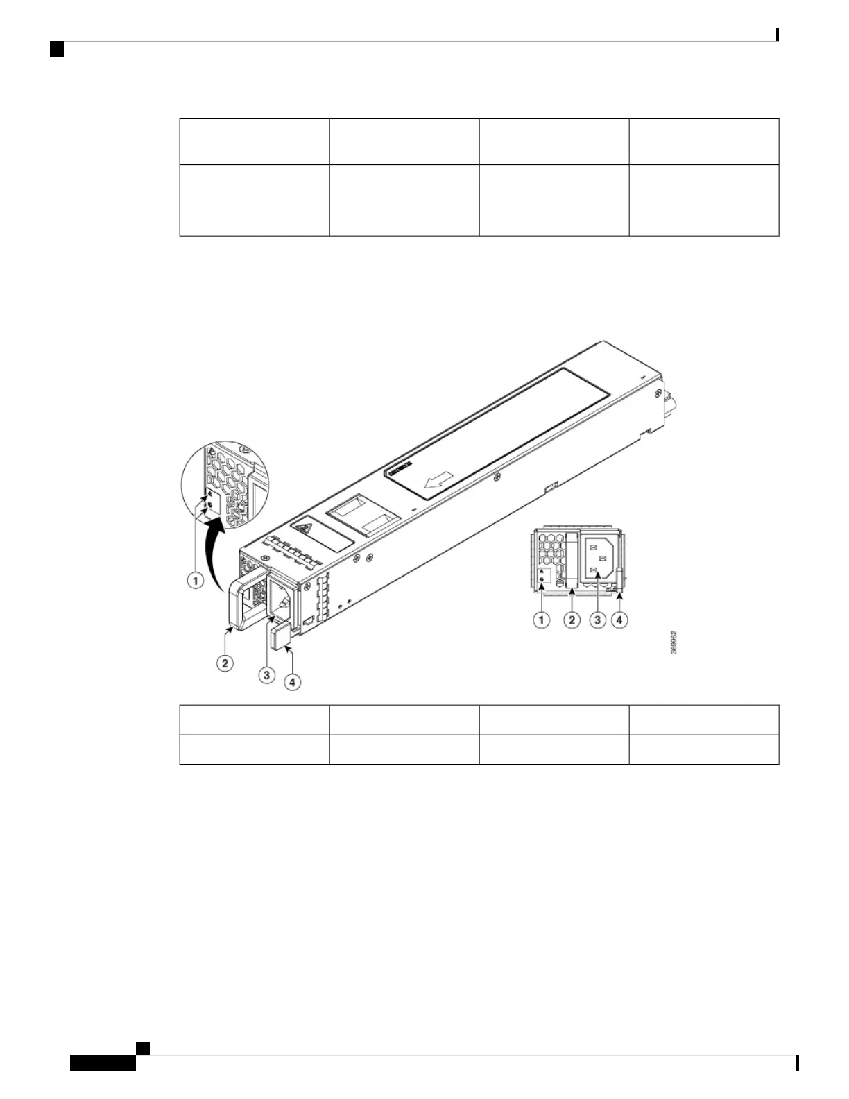
AC Power Supply
Figure 3: AC Power Supply Used in the Cisco C8500-12X4QC Router
AC power connector3FAIL and OK LEDs1
Retaining latch4Handle2
DC Power Supply
The DC (PWR-CH1-950WDCR) input connector is a two-wire connector with connection polarity from left
to right (when facing the unit) of positive (+) negative (–).
The power supply has a handle to be used for insertion and extraction. The module must be supported with
one hand because of its length.
Cisco Catalyst 8500 Series Edge Platforms Hardware Installation Guide
6
Overview
AC Power Supply
 Loading...


