The direction of the airflow is different for the and the as shown by the arrows in the illustrations below.
Note
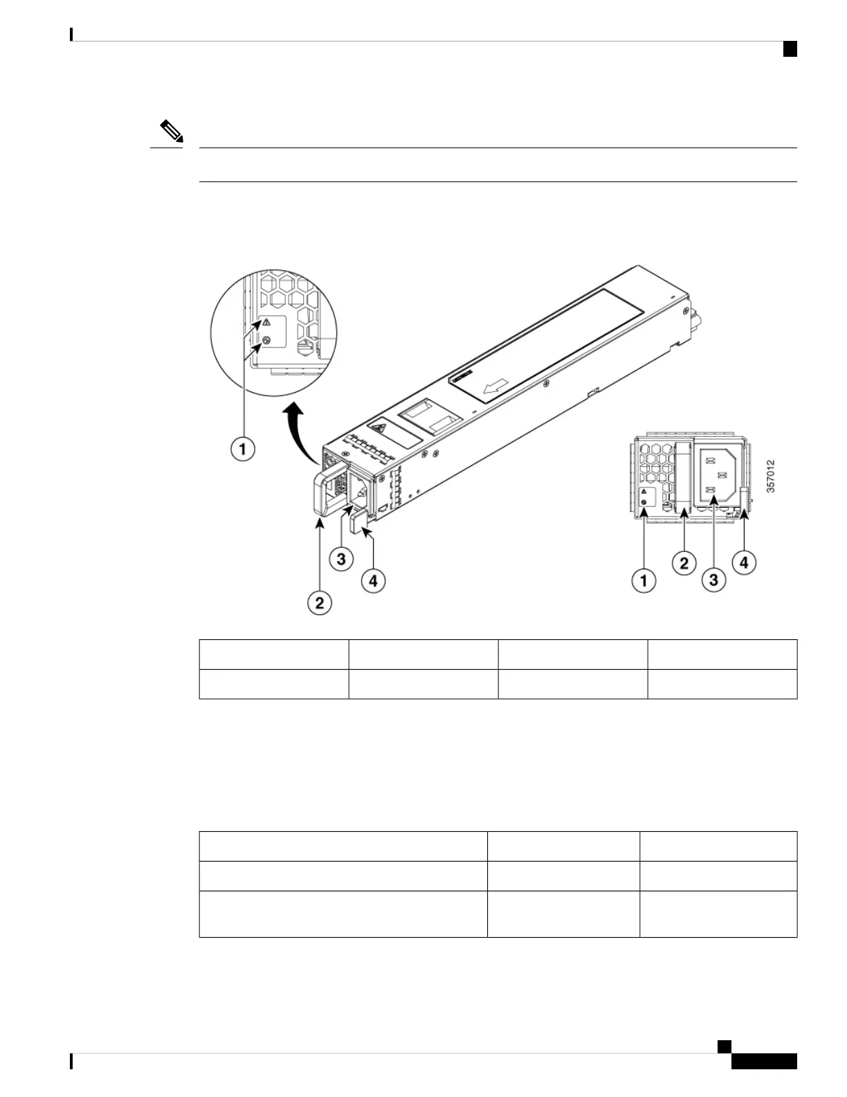
The following figure shows the DC power supply.
Figure 4: DC (PWR-CH1-950WDCR) Power Supply
FAIL and OK LEDs3DC power connections1
Retaining latch4Handle2
Power Supply LEDs
The following table describes the power supply LEDs.
Table 2: AC and DC Power Supply LEDs
Amber (FAIL) LED StatusGreen (OK) LED StatusPower Supply Condition
OFFOFFNo AC power to all power supplies
ONOFFPower Supply Failure (includes over voltage, over
current, over temperature and fan failure)
Cisco Catalyst 8500 Series Edge Platforms Hardware Installation Guide
7
Overview
Power Supply LEDs
 Loading...


